00194398-01.pdf - 第55页
Retrofit instructions SIPLACE HS-60 12/2004 Edition 2.5 Mechanical conversion 55 : Insert the pi ns in the base of the ceram ic substr ate centering unit into hole s in the liftin g table bed, and tighten the pins. : Con…
Retrofit instructions SIPLACE HS-60
2.5 Mechanical conversion 12/2004 Edition
54
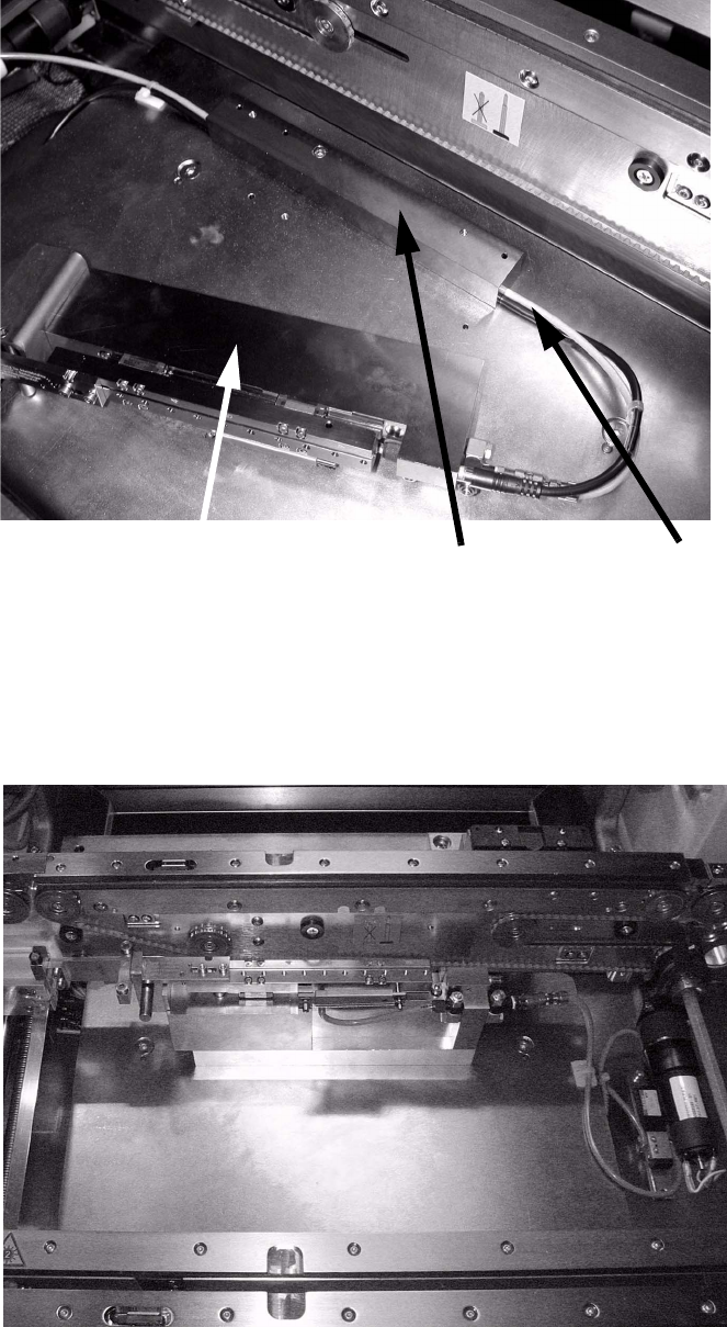
: In placement area 1, run the hoses and cables in the groove beneath the base.
2
2
: In placement area 2, the cable and hose may be attached directly.
2
Base
Run cables and hoses
beneath the base
Carriage unit
for ceramic substrate centering
Retrofit instructions SIPLACE HS-60
12/2004 Edition 2.5 Mechanical conversion
55
: Insert the pins in the base of the ceramic substrate centering unit into holes in the lifting table
bed, and tighten the pins.
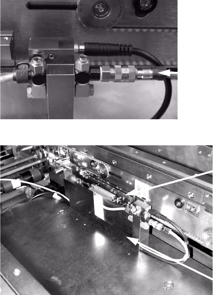
: Connect the second end of the air hose that comes from the solenoid valve to the second con-
nector on the ceramic substrate centering unit using the quick-release coupling (KS2-CK-3).
2
: Insert the carriage unit onto the base.
2
2
Quick-release coupling
(KS2-CK-3)
Base
Carriage unit,
ceramic sub-
strate centering

Retrofit instructions SIPLACE HS-60
2.6 Set the response distance of the proximity switch 12/2004 Edition
56
2.6 Set the response distance of the proximity switch
: Make sure that the active surface of the inductive proximity switch is set back 0.2 mm from the
stop surface of the carriage unit in the hole.
This prevents the proximity switch acting as a stop during the opening movement, and thus
being damaged.
: Correct the position of the proximity switch if necessary (grub screw, size 1 hexagon socket
spanner).
The proximity switch has an LED for checking the switching process.
2.7 Adapting to the size of the substrate
The ceramic substrate centering must be adapted to suit the size of substrate that is to be pro-
cessed in order to ensure 3-point contact of the substrate for centering in the X direction. This is
done by fitting the appropriate stop rail (with 2 ball bearings) and a suitable stop unit (with fixed
roller AND spacer bolt) -> see table below for item numbers.
CAUTION
The stop spacer bolt (set 1 to 3) must not be removed. 2
: Detach the complete stop rail fixing on the X-axis carriage unit (2 hexagon socket head screws
M 3, see Fig. 2.7 - 2 -> 4, 5).
Designation for substrate width Item no.
Stop rail 1, complete
with parallel pin
from 50 mm to 62 mm 00358877-01
Stop rail 2, complete from 62 mm to 106 mm 00358884-01
Stop rail 3, complete from > 106 mm to 140 mm 00358885-01
Stop set 1 (complete
with distance bolt)
from 50 mm to 62 mm 00358874-01
Stop set 2 (complete
with distance bolt)
from 62 mm to 106 mm 00358875-01
Stop set 3 (complete
with distance bolt)
from > 106 mm to 140 mm 00358876-01