00194398-01.pdf - 第58页
Retrofit instructions SIPLACE HS-60 2.7 Adapting to the size of the substrate 12/2004 Edition 58 : Fit the necessary stop unit 1, 2 or 3 (see t able above). 2 Fig. 2.7 - 2 Matching the ceramic substrat e center ing to th…
Retrofit instructions SIPLACE HS-60
12/2004 Edition 2.7 Adapting to the size of the substrate
57
: Fit the necessary complete stop rail (see table above and Fig. 2.7 - 1).
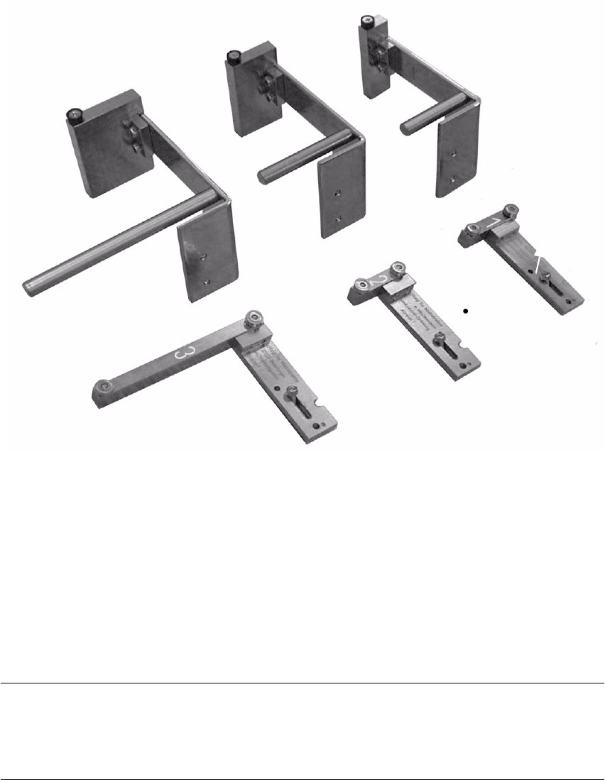
Fig. 2.7 - 1 Stop (unit) set 1, 2, 3 and matching stop rail, complete 1, 2, 3
1. Stop (unit) set 1, fixed stop
2. Stop (unit) set 2, fixed stop
3. Stop (unit) set 3, fixed stop
4. Stop rail 1, 2 and 3, complete (see marking 1, 2 and 3), movable stop
5. Travel limiting parallel pin:
MUST be present on stop rail 1
NOTE:
For substrates 50 mm to 62 mm wide that are more than 50 mm long (e.g. twice as long), the stop
set 1 (fixed stop) is fitted together with the complete stop rail "2" (= movable stop) (see table above
and Fig. 2.7 - 1). 2
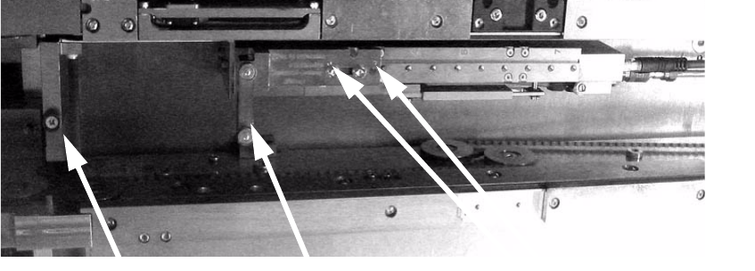
: Detach the stop (= stop unit) fixing on the X-axis carriage unit (2 hexagon socket head screws
M3, see Fig. 2.7 - 2 -> 6, 7).
2
3
1
5
4
4
4
Retrofit instructions SIPLACE HS-60
2.7 Adapting to the size of the substrate 12/2004 Edition
58
: Fit the necessary stop unit 1, 2 or 3 (see table above).
2
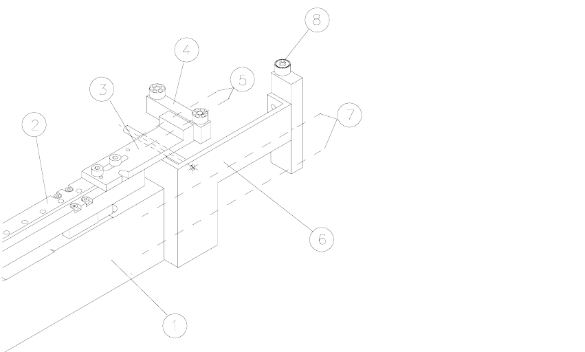
Fig. 2.7 - 2 Matching the ceramic substrate centering to the size of substrate
Key: 2
1. Base unit
2. X carriage unit
3. Fixing bracket for stop rail, 2 hexagon socket head screws M3 x 8
4. Stop rail (according to size of substrate: see table above)
5. 2 hexagon socket head screws M3
6. Stop unit with spacer bolt (according to size of substrate: see table above)
7. Fixing for stop unit: 2 hexagon socket head screws M3
8. Fixed stop roller
2
2
2
2
2
2
Retrofit instructions SIPLACE HS-60
12/2004 Edition 2.7 Adapting to the size of the substrate
59
: With the movable stop, make sure that the pins engage in the groove in the carriage unit.
2
Fig. 2.7 - 3 Ceramic substrate centering (side view)
Fixed stop
Movable stop
Pins in the groove