00198376-01_UM_TouchlessPlacement-R17-1_DE_EN.pdf - 第24页
Introduction General 24 Touchless Placement (R17-1) Berührungsloses Bestücken (R17-1) 1.1 1 . 1 G e n e r a l General 1.1.1 1 . 1 . 1 S y m b o ls / N o t e s Symbols / Notes Different symbols and notes have been used to…
Introduction
Touchless Placement (R17-1) Berührungsloses Bestücken (R17-1) 23
1
1 Introduction
Introduction
This manual describes the concept of components used for touchless placement and how to work with
them. We recommend that you read through it once you are familiar with the main features in SIPLACE
Pro and the station software. You will find all important information about the relations and the individual
procedures with touchless component placement here.
The contents of this manual address the following user groups:
▪ Operator
The operator has completed appropriate training and is authorized to carry out tasks on the machine
and line, such as the configuration and refilling of components, setup verification and production
preparation in the pre-setup area.
▪ The line engineer
The line engineer has completed special training and is authorized to carry out tasks, such as the
creation of setup configurations and definition of inspection parameters etc.
▪ The service engineer
Persons of this class have been trained to carry out servicing work, to set up machines and to change
the setup of machines.
CAUTION
Trained and qualified personnel
Only people with the appropriate training for the specific software part may carry out tasks on
the machine. All tasks must be carried out by trained and qualified personnel. All warning, cau-
tion and danger notes MUST be observed!
CAUTION
Contents of this software guide
We would like to draw your attention to the fact that the contents of this software guide are not
part of a previous or existing agreement, commitment or legal contract, neither is this intended
to modify one of the above. All obligations of ASM Assembly Systems GmbH & Co. KG may be
taken from the appropriate sales contract, which also contains a complete and valid warranty
agreement. These contractual statements are neither extended nor restricted by this software
guide.
Introduction
General
24 Touchless Placement (R17-1) Berührungsloses Bestücken (R17-1)
1.1
1.1 General
General
1.1.1
1.1.1 Symbols / Notes
Symbols / Notes
Different symbols and notes have been used to make it easier to read and understand this document.
1.1.2
1.1.2 ASM on the World Wide Web
ASM on the World Wide Web
Log in to our homepage at http://www.asm-smt.com.
► You can choose between the German and English versions.
The different sections contain information about our products, services and contact persons.
In addition, registered customers can also access the
SIPLACE User Group
. Here you can call up spe-
cial information about our placement systems, e.g.
▪ Technical documentation,
▪ Technical information,
▪ Spare parts lists etc.
Registration for the user group is very simple:
► Click on the Register link.
► Fill in the registration form and send it off to us.
Soon afterwards, you will receive your access authorization with USER ID and password.
1.1.3
1.1.3 Release History
Release History
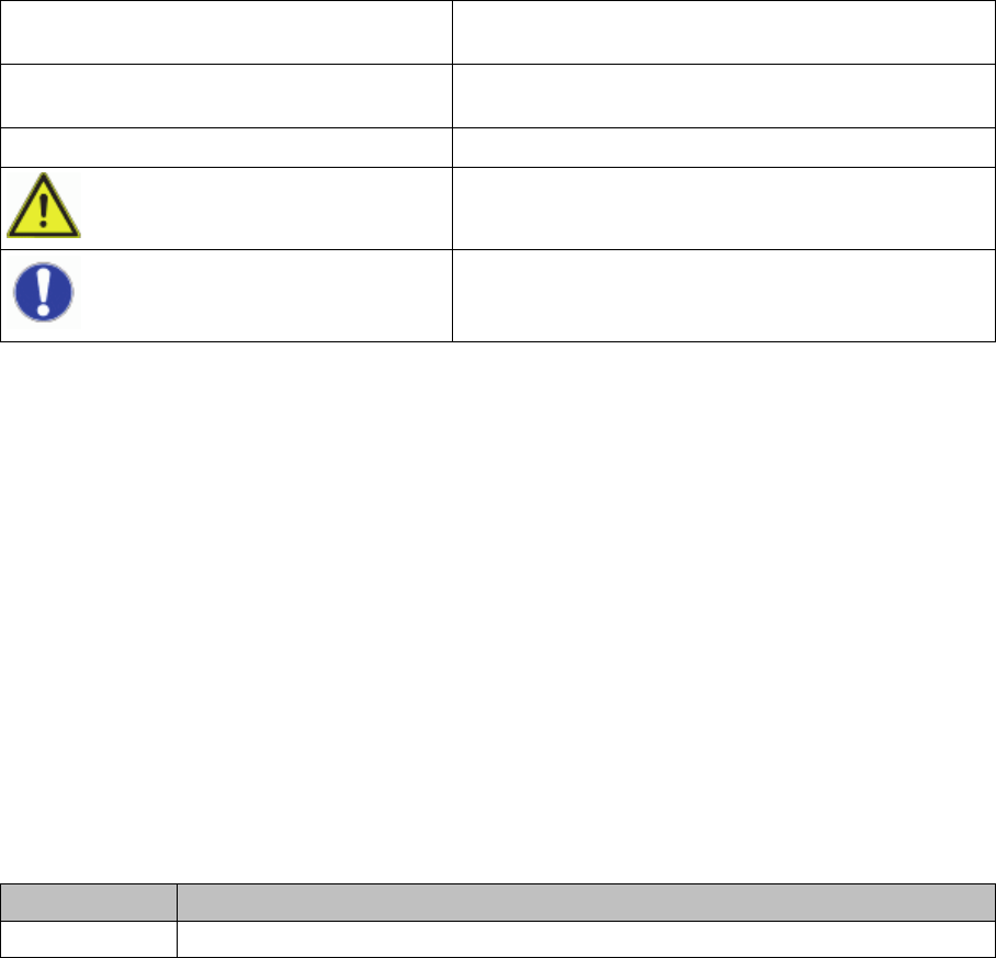
Words in bold/italic print These refer to dialogs, dialog fields, menu items, and
commands.
Step ... Includes all actions to do with a particular dialog. A dia-
log may be composed of several actions ( ).
► Requires an action (e.g. mouse click, open file)
Indicates a warning. The information is essential for
successful working.
Explanatory information.
Edition Changes
06/2017 First edition
What is touchless placement of components?
Prerequisites
Touchless Placement (R17-1) Berührungsloses Bestücken (R17-1) 25
2
2 What is touchless placement of components?
What is touchless placement of components?
For the placement of highly sensitive components in the chip assembly process, placement without con-
tact can be carried out. For a "touchless" component placement, the placement process Touchless must
be assigned to the component shape. At least three height measurement points must be available on
the boards or grid boards onto which the components are to be placed. The Z height is measured from
the level of these height measurement points.
This process is designed for highly sensitive components and can only be used for boards with high lev-
els of planarity (e.g. with chuck or vacuum tooling).
2.1
2.1 Prerequisites
Prerequisites
▪ SIPLACE Pro version 14.1 or higher
▪ Station software version 710.1 or higher
▪ Planarity of the board for placement (< 20µm)
– Board transport with chuck / vacuum tooling is recommended
▪ Constant component thickness
▪ For C&P 20 A/M/P/M2 placement head