00198376-01_UM_TouchlessPlacement-R17-1_DE_EN.pdf - 第30页
Programming in SIPLACE Pro Defining Height Measurement Points 30 Touchless Placement (R17-1) Berührungsloses Bestücken (R17-1) Height Measurement Points for Boards ► Open the required board (1) in the SIPLACE Pro Board E…
Programming in SIPLACE Pro
Defining Height Measurement Points
Touchless Placement (R17-1) Berührungsloses Bestücken (R17-1) 29
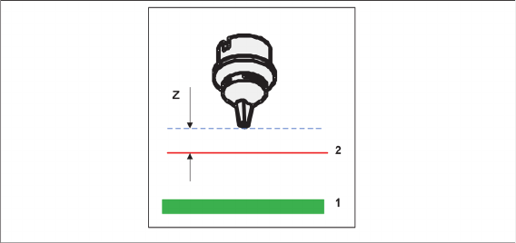
Touchless placement, Z distance
This value defines the distance to the calculated placement level.
1. Board
2. Calculated placement level (in accordance with height measurement)
3. Z distance (distance between the component lower edge and the calculated placement level)
3.2
3.2 Defining Height Measurement Points
Defining Height Measurement Points
If components are placed on a board or grid board using the Touchless placement process, height meas-
urement points must be defined around the placement position on the board or grid board. Height meas-
urement points are necessary for a correct calculation of the respective placement levels. At least three
height measurement points must be defined and active for the relevant board side or panel.
Rules for height measurement points
Observe the following rules:
▪ The more height measurement points are selected (more than three height measurement points),
the higher the process reliability will be.
▪ The greater the distance between the height measurement points, the better.
▪ The shorter the distance between the placement positions to their connected height measurement
points, the better the calculation of the board height.
▪ The area spanned between the three height measurement points should be as large as possible.
▪ Avoid (almost) collinear positions for height measurement points.
▪ The spanned area should not be an obtuse-angled triangle.
Programming in SIPLACE Pro
Defining Height Measurement Points
30 Touchless Placement (R17-1) Berührungsloses Bestücken (R17-1)
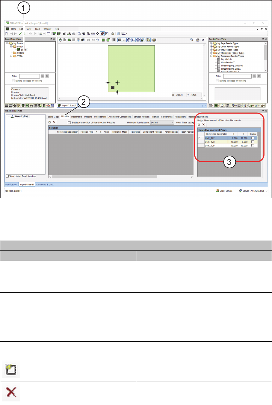
Height Measurement Points for Boards
► Open the required board (1) in the SIPLACE Pro Board Editor.
Board Editor – Defining Height Measurement Points
► Select the Fiducials tab (2) on the board side or panel.
► In the Height Measurement Points table (3), define at least three height measurement points to
measure the height for contactless component placement.
Table: Height Measurement Points
Field Value/Meaning
Reference designator Enter the unique designator for the height meas-
urement point here. This designator is to represent
the position of the height measurement point on
the board.
X Position of the height measurement point in X di-
rection with regards to the position of the current
panel or board.
Y Position of the height measurement point in Y di-
rection with regards to the position of the current
panel or board.
Disable Disables this height measurement point for meas-
urement.
Adds a new line to the table.
Removes a selected line from the table.
Programming in SIPLACE Pro
Defining Height Measurement Points
Touchless Placement (R17-1) Berührungsloses Bestücken (R17-1) 31
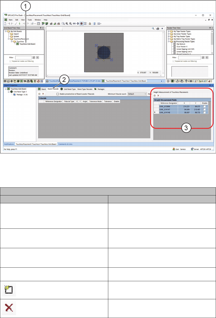
Height Measurement Points for Grid Boards
► Open the required grid board (1) in the SIPLACE Pro Grid Board Editor.
Grid Board Editor – Defining Height Measurement Points
► Select the PCB Fiducials tab (2) or the Panel Type Fiducials tab.
► In the Height Measurement Points table (3), define at least three height measurement points to
measure the height for contactless component placement.
Table: Height Measurement Points
Field Value/Meaning
Reference designator Enter here the unique designator for the height
measurement point. This designator is to repre-
sent the position of the height measurement point
on the grid board
X Position of the height measurement point in X di-
rection with regards to the position of the current
grid board.
Y Position of the height measurement point in Y di-
rection with regards to the position of the current
grid board.
Disable Disables this height measurement point for meas-
urement.
Adds a new line to the table.
Removes a selected line from the table.