00198376-01_UM_TouchlessPlacement-R17-1_DE_EN.pdf - 第32页
Programming in SIPLACE Pro Defining Height Measurement Points 32 Touchless Placement (R17-1) Berührungsloses Bestücken (R17-1)
Programming in SIPLACE Pro
Defining Height Measurement Points
Touchless Placement (R17-1) Berührungsloses Bestücken (R17-1) 31
Height Measurement Points for Grid Boards
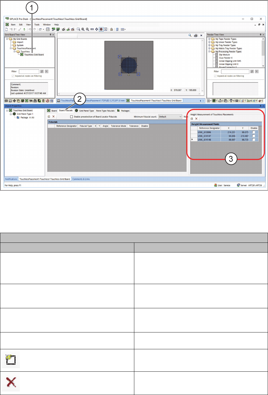
► Open the required grid board (1) in the SIPLACE Pro Grid Board Editor.
Grid Board Editor – Defining Height Measurement Points
► Select the PCB Fiducials tab (2) or the Panel Type Fiducials tab.
► In the Height Measurement Points table (3), define at least three height measurement points to
measure the height for contactless component placement.
Table: Height Measurement Points
Field Value/Meaning
Reference designator Enter here the unique designator for the height
measurement point. This designator is to repre-
sent the position of the height measurement point
on the grid board
X Position of the height measurement point in X di-
rection with regards to the position of the current
grid board.
Y Position of the height measurement point in Y di-
rection with regards to the position of the current
grid board.
Disable Disables this height measurement point for meas-
urement.
Adds a new line to the table.
Removes a selected line from the table.
Programming in SIPLACE Pro
Defining Height Measurement Points
32 Touchless Placement (R17-1) Berührungsloses Bestücken (R17-1)
Placement Process at the Station
Possible Errors and Corrections
Touchless Placement (R17-1) Berührungsloses Bestücken (R17-1) 33
4
4 Placement Process at the Station
Placement Process at the Station
After transporting the board into the station, fiducial detection takes place automatically and the defined
height measurement points are measured. The height measurement process calculates the placement
levels for contactless placement.
The placement process is started and the respective components are placed without contact.
4.1
4.1 Possible Errors and Corrections
Possible Errors and Corrections
Three error messages could occur in the station software:
32438 „Z-position out of range during height measurement“
▪Cause
– The result of the height measurement cannot be used because the difference between the ex-
pected Z height and the measured Z height of the board is too big.
▪Correction
– Make sure the board's position in the machine is planar.
▪ Correction with chuck
– Check the board height that is set in the programming system.
– Check if the correct chuck type is selected.
32439 „Slope of measured board surface is too large“
▪Cause
– The height measurement result cannot be used.
▪Correction
– Check the clamping and ensure that the board's position in the machine is planar.
– Check if the correct height measurement points are selected.
– Check whether the height measurement points lie on an interfering contour.
▪ Correction for wafer
– Check if the wafer is positioned correctly in the centering pin.
40058 „The component touched the board despite of the expected touchless placement pro-
cess“
The following causes could lead to this error:
▪ Wrong component thickness
▪ Too low level of planarity of the board or wafer
▪ The board or the wafer are not correctly picked up on the chuck / vacuum tooling (e.g. due to the
wafer centering pin).
The following procedure is carried out on the station software:
1. The station determines when the component makes contact with the board or the wafer.
2. The placement is stopped.
3. The affected placement position is set to "Unknown placement status".
4. The message 40020 „Unknown placement status“ is shown to check the placement position: