A16-F-R-00-H-S-K-A200-32408柱塞泵资料.pdf - 第3页
27 PIST ON PUMPS A Series A Series V ariable Displacement Piston Pumps Starting Before first staring, fill pump case with clean operating oil via the filling port. In order to avoid air blockage when first starting, adju…
26
A
Series Variable Displacement Piston Pumps
Hydraulic Fluids
Hydraulic Fluids Control of Contamination
Use petroleum based oils such as anti-wear type hydraulic
oils equivalent to ISO VG-32 or 46. The recommended
viscosity range is from 20 to 400 mm
2
/s and temperature
range is from 0 to 60℃, both of which have to be satisfied
for the use of the above hydraulic oils.
Due caution must be paid to maintaining control over
contamination of the operating oil which can otherwise
lead to breakdowns and shorten the life of the unit.
Please maintain the degree of contamination within NAS
Grade 10.
The suction port must be equipped with at least a 100 μm
(150 mesh) reservoir type filter and the return line must
have a line type filter of under 10 μm.
Instructions
Mounting Drain Piping
When installing the pump the filling port should be
positioned upwards.
Alignment of Shaft
Employ a flexible coupling whenever possible, and avoid
any stress from bending or thrust.
Maximum permissible misalignment is less than 0.1 mm
TIR and maximum permissible misangular is less than
0.2°.
Suction Pressure
Permissible suction pressure at inlet port of the pump is
between -16.7 and +50 kPa.
For piping to the suction port, use the pipes of the same
diametre as that of the specified pipe flange to be used.
Make sure that the height of the pump suction port is within
one metre from the oil level in the reservoir.
Hints on Piping
When using steel pipes for the suction or discharge ports,
excessive load from the piping to the pump generates
excessive noise.
Whenever there is fear of excessive load, please use rubber
hoses.
Suction Piping
In case the pump is installed above the oil level, the
suction piping and suction line filter should be located
lower than the pump position to prevent air in the suction
line.
Install drain piping according to the chart and ensure that
pressure within the pump housing should be maintained at
a normal pressure of less than 0.1 MPa and surge pressure
of less than 0.5 MPa.
Length of piping should be less than 1 m, and the pipe end
should be submerged in oil.
Bleeding Air
It may be necessary to bleed air from pump case and
outlet line to remove causes of vibration. An air bleed
valve (Model Number ST1004-
*
-10
*
, Page 265) is
recommended for this purpose.
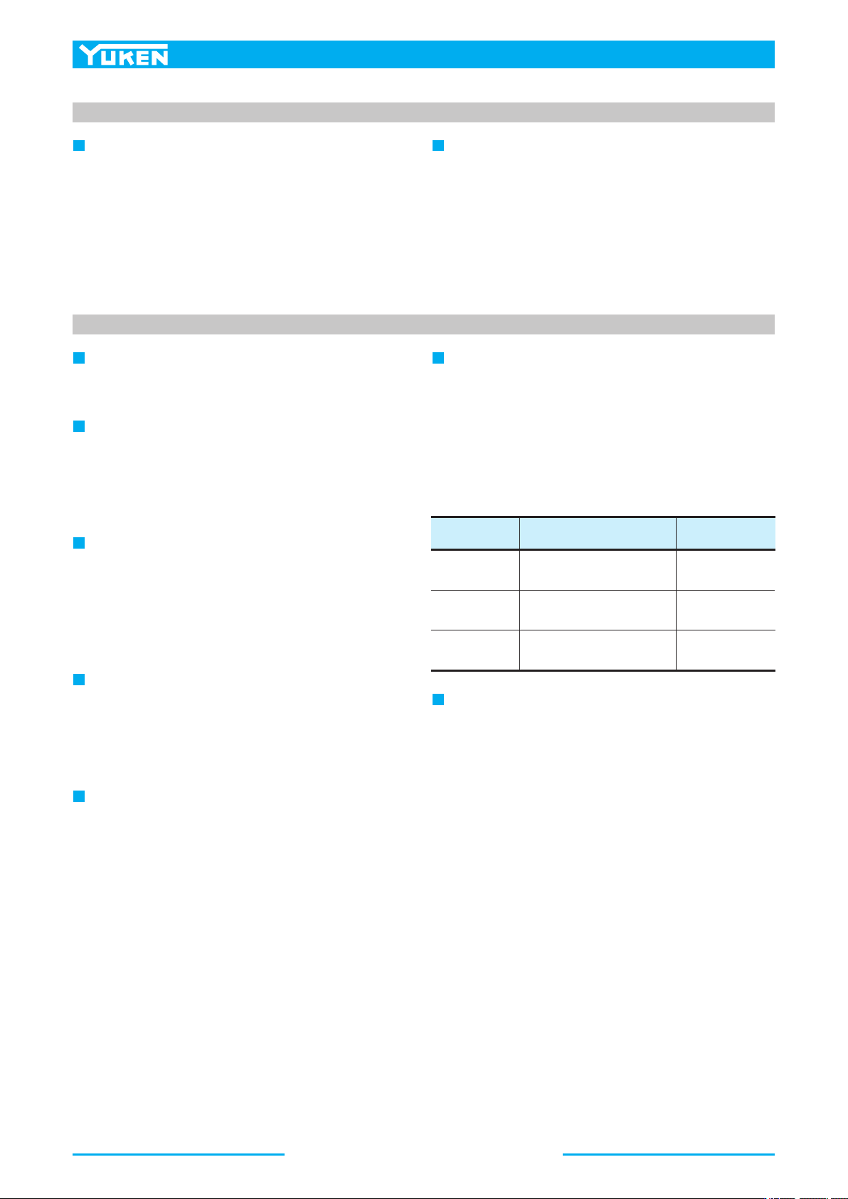
[Recommended Drain Piping Size]
Model Fitting Size
3/8
[Inside Dia. 8.5 mm or more]
Inside Dia. of Pipe
A10, A16, A22 10 mm or more
1/2
[Inside Dia. 12 mm or more]
12 mm or more
3/4
[Inside Dia. 16 mm or more]
19 mm or more
A37, A45
A56, A70, A90,
A100, A145
When using steel pipes for the suction or discharge ports,
excessive load from the piping to the pump generates
excessive noise.
Whenever there is fear of excessive load, please use
rubber hoses.
27
PISTON PUMPS
A Series
A
Series Variable Displacement Piston Pumps
Starting
Before first staring, fill pump case with clean operating
oil via the filling port.
In order to avoid air blockage when first starting, adjust
the control valves so that the discharged oil from the
pump is returned direct to the reservoir or the actuator
moves in a free load.
Setting Discharge Pressure and Delivery
At the time of shipment, the unit has been preset to
maximum delivery and minimum discharge pressure.
Adjust the preset delivery and pressure to meet your
system requirements.
Turning the adjustment screw clockwise, increases
pressure.
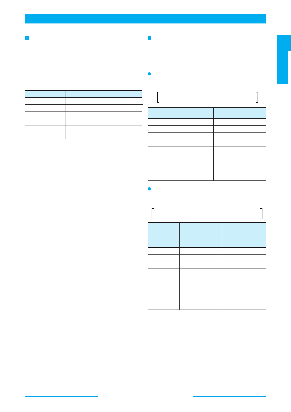
Adjustment of Discharge Pressure
Volume adjusted by each full turn of the pressure
adjustment screw
Model
A10
A16/A22
A37/A45/A56
A70
A90/A100
A145
370
600
1200
2100
2500
3300
Volume cm
3
[Volume of Pre-fill Oil Required]
Turning the flow adjustment screw clockwise, decreases
delivery.
Adjustment of Delivery
The minimum adjustable flow and adjustable volume of
each full turn of the delivery adjustment screw
Model Numbers
A10-FR01B
A10-FR01C/H
A16/A22/A37/A56-
*
-R-01-B
A16/A22/A37/A56-
*
-R-01-C
A16/A37/A56-
*
-R-01-H
A70/A90/A100/A145-
*
-R01B
A70/A90/A100/A145-
*
-R01C
A70/A90/A100/A145-
*
-R01H
A70/A90/A100/A145-
*
-R01K
2.9
5.4
3.5
6.5
7.9
2.3
3.2
4.0
4.7
Adjustment Volume
MPa
1.1
1.4
2.0
2.9
3.9
4.4
4.8
5.2
A10
A16
A22
A37
A56
A70
A90
A100
2.0
4.0
6.0
10
12
36
56
62
7.2A145 83
Model
Adjustable volume
with each full turn
of the adjustment
screw
3
cm /rev
Minimum adjustment flow
3
cm /rev
28
A
Series Variable Displacement Piston Pumps
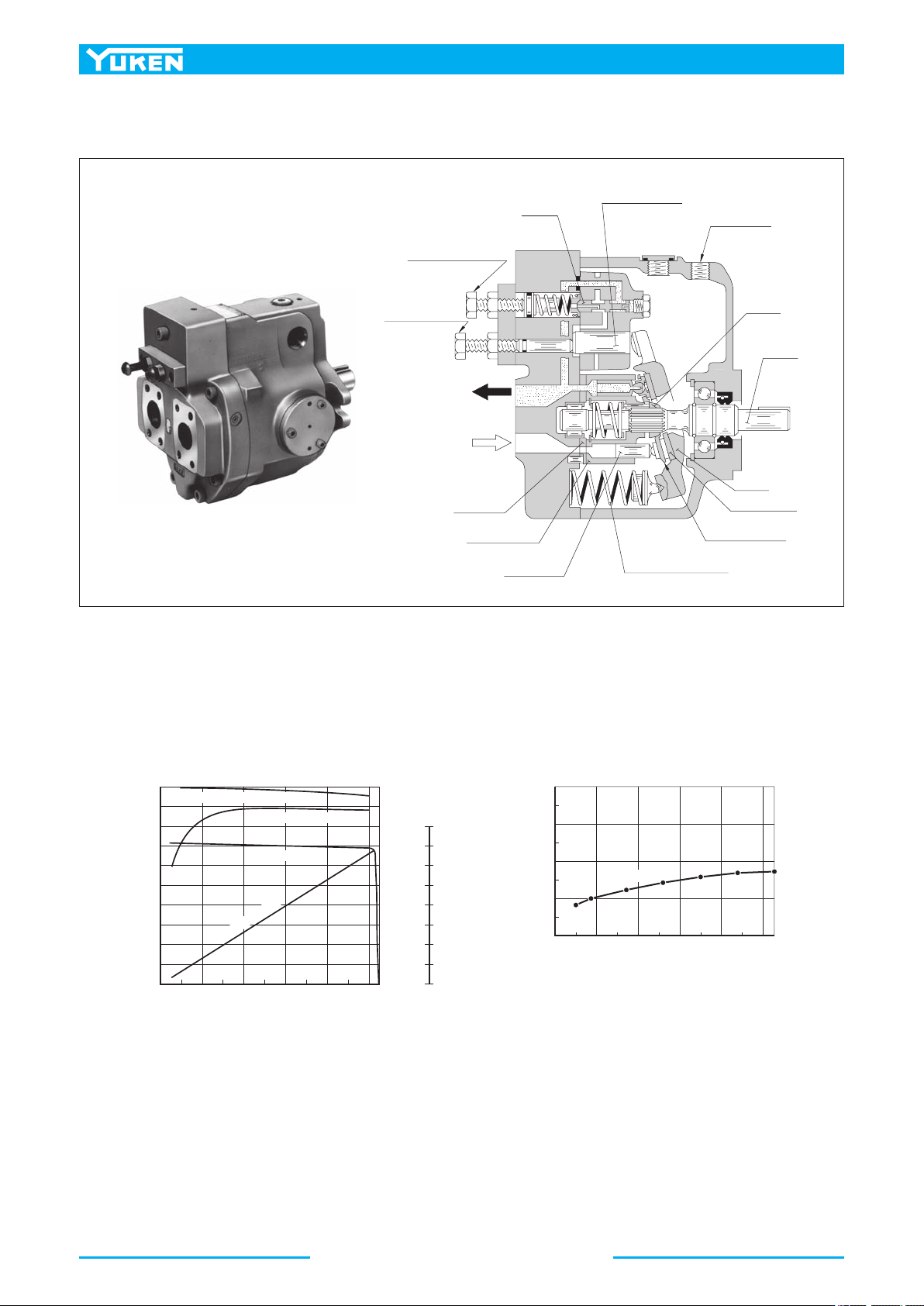
“A16” type performance characteristics
OUT
IN
Control Piston
Drain Port
Pivot
Shaft
Yoke
Swash Plate
Slipper Retainer
Spring, Yoke Return
Piston Ass'y
Cylinder Block
Port Plate
Flow Adj. Screw
Pressure Adj. Screw
Spool
A
Series Variable Displacement Piston Pumps
■ Features
● High efficiency
The efficiency properties in case of “A16”from are high
efficiencies to be shown below.
● Accomplishment of energy-saving
Because the overall efficiency is high and the cut-off
characteristics is sharp, thus the input power may be saved.
● Low noise level
In the “A16” pump, the noise level is as low as 57.3 dB(A)
[at the full cut-off pressure 21 MPa with speed 1500 r/min
one metre horizontally away from pump head cover.]
● Low heat generation
Because of small power loss, it is possible to reduce the rise
in oil temperature. Accordingly, capacity of a reservoir can
be reduced.
0
0
4
8
3
12
16
6
20
24
9
28
32
12
20
40
60
80
100
0 4 8 12 16 20
21
N=1800r/min
40
50
60
70
80
N=1500r/min
0 4 8 12 16 20 21
Volumetric Efficiency
Overall Efficiency
Output Flow
Input Power
Output Flow
L/min
Input Power kW
Pressure
MPa
Efficiency
%
Pressure MPa
Noise Level dB(A)
Full Cut-off