A16-F-R-00-H-S-K-A200-32408柱塞泵资料.pdf - 第34页
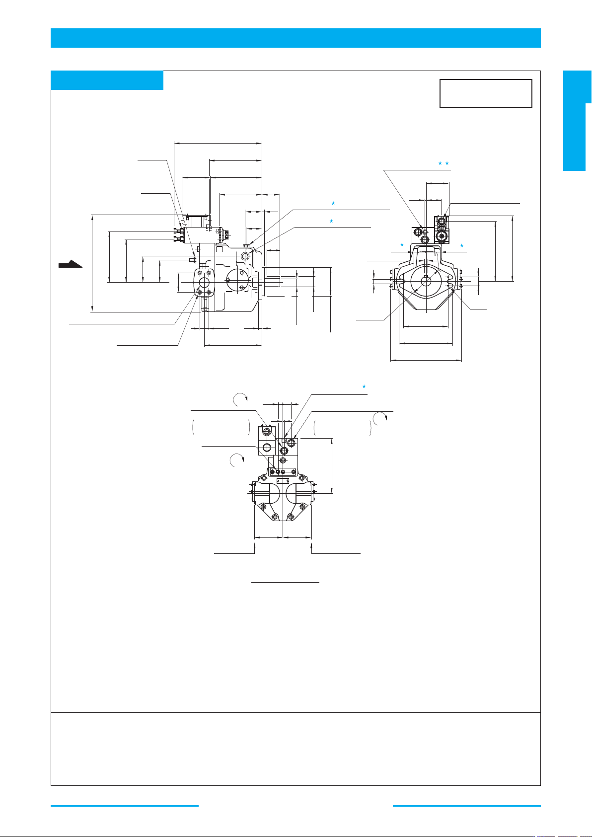
58 A Series V ariable Displacement Piston Pumps Solenoid T wo Pressure Control T ype 3 4 5 1 2 3 239 233.5 Fully Extended 354.5 95 209.5 65 62 40 19.5 16 18 26.2 246.5 52.4 90 Drain Port Rc3/4 Thd. (Both Sides) Discharge…
57
PISTON PUMPS
A Series
A
Series Variable Displacement Piston Pumps
Solenoid Two Pressure Control Type
1
2
3
5
5
3 4
"PP1"
"PP2"
Pressure Adj. Screw (PL)
14
Hex.
INC.
Works at Solenoid
De-energised
Pilot Port "PP1"
Rc1/4
Thd.
13 26
6
190
100 100
Surface of
Discharge Port
Surface of
Suction Port
Pressure Adj.
Screw (PH)
14
Hex.
INC.
Works at Solenoid
Energised
Flow Adj. Screw
5
Hex. Soc.
DEC.
71.5
48.5
6
Pilot Port "PP2"
Rc1/4
Thd.
49
25
223.5
146
174
232
14
41
120
Dia.
R14
40
101.60
Dia.
101.55
30.2
12
207
146
321.5
M10 Thd. 19 Deep
4 Places
Front Side : Discharge Port 32 Dia.
Rear Side : Suction Port 35 Dia.
X
174
90
77
58.7
43.5
50.5 9.5
147.5 62
171.595
177
Fully Extended
292
Lock Nut
14
Hex.
Lock Nut
17
Hex.
Filling Port
(
22
Hex. Head Plug Furnished)
Drain Port
Rc3/4
Thd. (Both Sides)
7.94
7.97
205
31.75
Dia.
35.32
35.14
31.70
Electrical Conduit
Connection
G1/2
Thd. (Both Ends)
Side Port Type
Flange Mtg. : A56-F-R-02-S-K
DIMENSIONS IN
MILLIMETRES
★1. Install the pump so that the "Filling Port" is at the top.
★2. Use either port of two drain ports at your option. Keep the remaining port plugged.
★3. The pilot port provided is for connecting a control valve, if multistage pressure control is required.
★4. The pilot port "PP2" is not provided for N.American Design Standard.
★5. Dimensions show surface of drain port.
● Axial Port Type
Port mounting dimensions are the same as those of pressure
compensator model.
Refer to page 46 for port mounting dimensions.
● Foot Mounting Type
Mounting bracket is common to that of pressure compensator model.
Refer to page 46 for the dimensions of mounting bracket.
View Arrow X
58
A
Series Variable Displacement Piston Pumps
Solenoid Two Pressure Control Type
3 4
5
1
2
3
239
233.5
Fully Extended
354.5
95
209.5
65
62
40
19.5
16
18
26.2
246.5
52.4
90
Drain Port
Rc3/4
Thd. (Both Sides)
Discharge Port
26
Dia.
M10
Thd.
17
Deep
4 Places
95 95
73 73
10
202.5
186.5
18
14
114.4
134
181
211
114.4
180
217.5
118 236
7.97
7.94
Surface of
Discharge Port
Surface of Drain Port
Surface of Drain Port
Surface of
Suction Port
27
Dia. Spotface (Rear Side)
4 Places
35
Dia. Spotface
(Rear Side)
2 Places
Pilot Port "PP2"
Rc1/4
Thd.
87.5
10
Pressure Adj. Screw (PL)
14
Hex.
Flow Adj. Screw
17
Hex.
DEC.
INC.
Works at Solenoid
De-energised
Pressure Adj. Screw (PH)
14
Hex.
INC.
Works at Solenoid
Energised
Suction Port
38
Dia.
Filling Port
(
22
Hex. Head Plug Furnished)
Eye Bolt
M10
M12
Thd.
19
Deep
4 Places
Case Drain Port
5
Hex. Soc.
35.7
246.5
69.9
Pilot port "PP1"
Rc1/4
Thd.
Y
X
9.5
64.5
31.75
31.70
Dia.
35.32
35.14
127.00
Dia.
126.95
Electrical Conduit Connection
G1/2
Thd. (Both Ends)
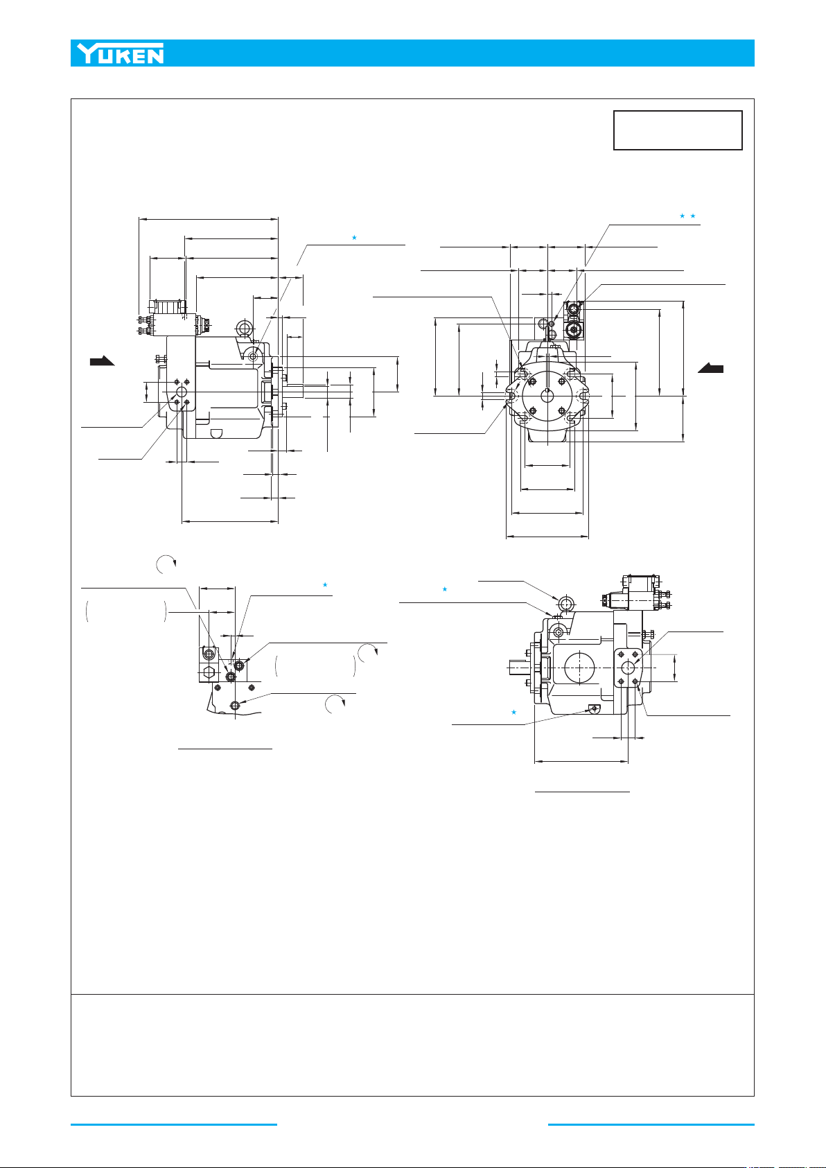
Flange Mtg. : A70-FR02*
DIMENSIONS IN
MILLIMETRES
★1. Install the pump so that the "Filling Port" is at the top.
★2. Use either port of two drain ports at your option. Keep the remaining port plugged.
★3. The pilot port provided is for connecting a control valve, if multistage pressure control is required.
★4. The pilot port "PP2" is not provided for N.American Design Standard.
★5. Case drain port is available for use when draining hydraulic fluid from pump casing.
● Foot Mounting Type
Mounting bracket is common to that of pressure compensator model.
Refer to page 47 for the dimensions of mounting bracket.
View Arrow X
View Arrow Y
59
PISTON PUMPS
A Series
A
Series Variable Displacement Piston Pumps
Solenoid Two Pressure Control Type
2
1
3
5
3 4
119.5
23
95
263.5
13
63
113
58.7
22
23
30.2
270
Discharge Port
32
Dia.
M10
Thd.
19
Deep
4 Places
Drain Port
Rc3/4
Thd. (Both Sides)
Case drain Port
5
Hex. Soc.
Surface of Discharge Port
Surface of Drain Port Surface of Drain Port
Surface of Suction Port
Pilot Port "PP2"
Rc1/4
Thd.
105
9.56
9.53
105
68 68
2.5
161.6
226
245.5
127
161.6
196
212
21.5
Dia. Through
39
Dia. Spotface
(Rear Side)
4 Places
R22
258
Fully Extended
379
95
77.8
88
168
196
270
42.9
Filling Port
(
27
Hex. Head Plug Furnished)
Eye Bolt
M10
Electrical Conduit Connection
G1/2
Thd. (Both Ends)
M12
Thd.
19
Deep
4 Places
Suction Port
48
Dia.
Pilot Port "PP1"
Rc1/4
Thd.
Pressure Adj. Screw (PL)
14
Hex.
INC.
Works at Solenoid
De-energised
Flow Adj. Screw
17
Hex.
DEC.
Pressure Adj. Screw (PH)
14
Hex.
INC.
Works at Solenoid
Energised
22.5
2.5
Y
X
52
38.10
38.05
Dia.
42.36
42.18
152.40
Dia.
152.35
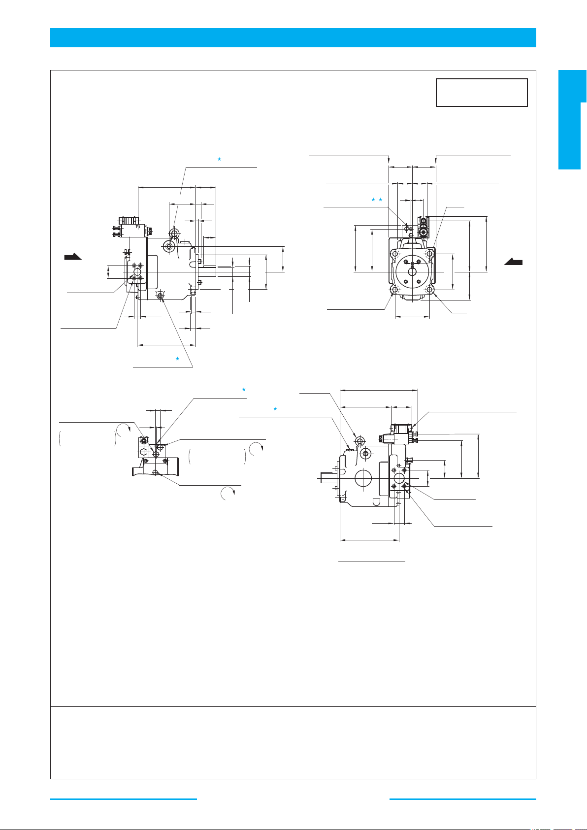
Flange Mtg. : A90-FR02*
DIMENSIONS IN
MILLIMETRES
★1. Install the pump so that the "Filling Port" is at the top.
★2. Use either port of two drain ports at your option. Keep the remaining port plugged.
★3. The pilot port provided is for connecting a control valve, if multistage pressure control is required.
★4. The pilot port "PP2" is not provided for N.American Design Standard.
★5. Case drain port is available for use when draining hydraulic fluid from pump casing.
● Foot Mounting Type
Mounting bracket is common to that of pressure compensator model.
Refer to page 48 for the dimensions of mounting bracket.
View Arrow X
View Arrow Y