A16-F-R-00-H-S-K-A200-32408柱塞泵资料.pdf - 第7页
31 PIST ON PUMPS A Series A Series V ariable Displacement Piston Pumps Graphic Symbol Applicable only f or “A200” ★1. Whenever setting pressure, make sure the full cut-off pressure never exceeds the maximum intermittent …
30
A
Series Variable Displacement Piston Pumps
M
O
M
O
Pressure
Output Flow
Pressure
Output Flow
Output Flow
Input Power
QH
QL
QH
QL
PL PH
Pressure
→
OutputFlow
→
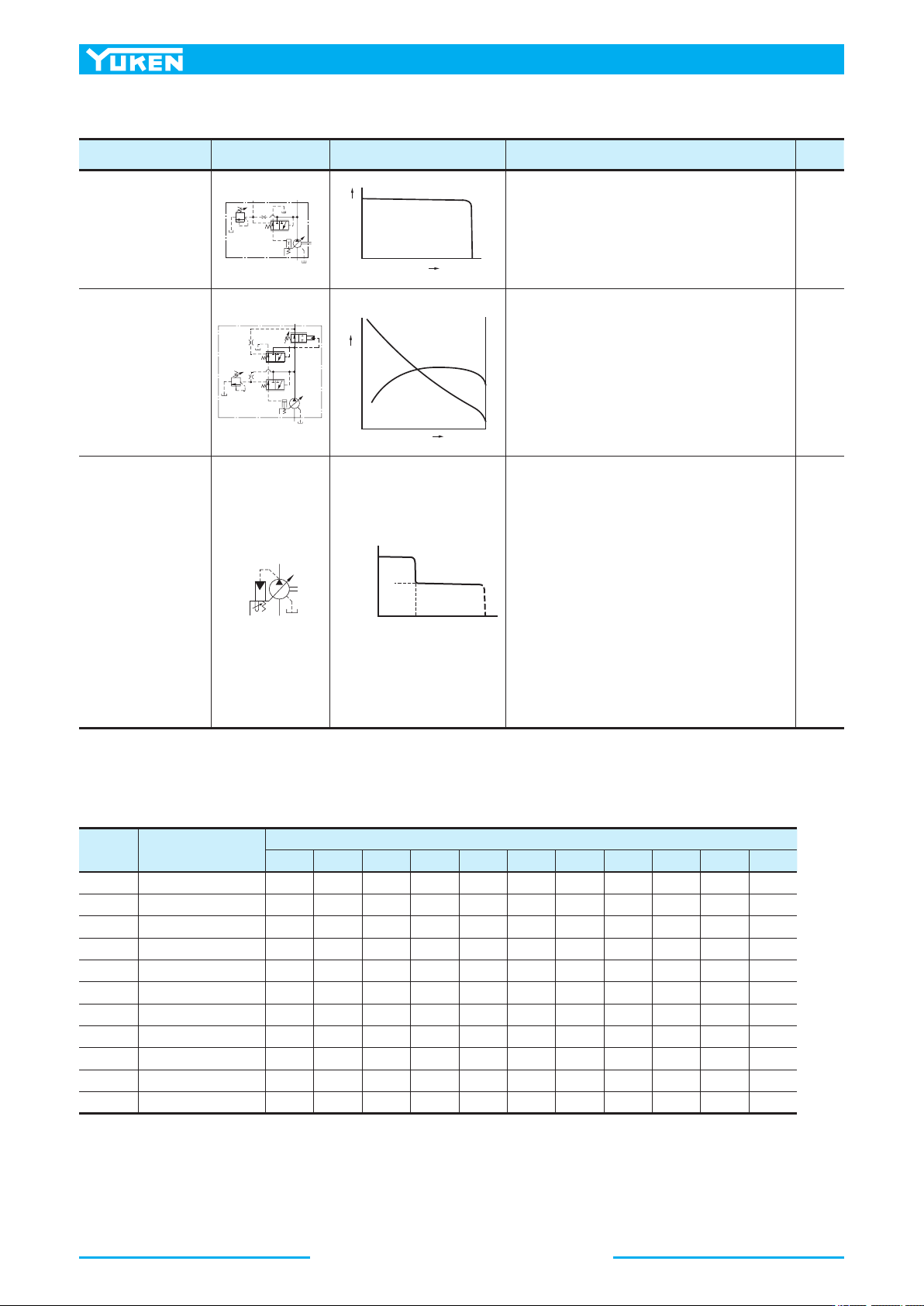
■ Control Type
Control Type Graphic Symbols Performance Characteristics Explanation Page
"07"
Pilot Pressure
Control Type
Pressure
Compensator
The pump is used in combination with the pilot relief
valve or multistage pressure control valve. By
controlling the pilot pressure, the full cut-off pressure
can be remote-controlled according to your
requirements.
93
"09"
Constant
Power
Control Type
•
Pump input power can be controlled in accordance
with the motor output.
•
When the discharge pressure rise, the output flow
decreases corresponding to the preset input power.
•
The pump can act for function of two pumps, low-
pressure large-flow and high-pressure small-flow.
Therefore, the motor capacity can be reduced.
101
"00-
Z500"
Simple Two-
Pressure
Two-Flow
Control Type
•
This type of control enables one pump to act as two
pumps (low-pressure and large-flow/high-pressure
and small-flow-rate). Therefore, the motor capacity
can be reduced.
•
When the system pressure increases near the preset
“PL” pressure due to the load increase, the pump
flow automatically decreases to “QL.”
•
This type of control is suitable for an application
like the press, where switching from rapid
advance to feed is required just when the press
(pressurizing) starts.
•
The PH pressure can be remote-controlled with a
separately located relief valve. With this type of
control, it is easy to change the applied pressure
setting when materials or shapes of the press are
changed.
109
■ Availability of Control Type
Mark "○" in the table below refers to standard model.
Model
Numbers
Geometric
Displacement cm
3
/rev
Control Type
01 02 03 04 04E 04EH 05 06 07 09 00-Z500
A10 10.0
○ ○
A16 15.8
○ ○ ○ ○ ○ ○ ○ ○ ○ ○ ○
A22 22.2
○ ○ ○ ○ ○ ○ ○ ○
A37 36.9
○ ○ ○ ○ ○ ○ ○ ○ ○ ○ ○
A45 45.0
○ ○
A56 56.2
○ ○ ○ ○ ○ ○ ○ ○ ○ ○ ○
A70 70.0
○ ○ ○ ○ ○ ○ ○ ○ ○ ○
A90 91.0
○ ○ ○ ○ ○ ○ ○ ○ ○
A100 100
○ ○ ○
A145 145
○ ○ ○ ○ ○ ○ ○ ○ ○ ○
A220 219
○ ○ ○ ○
31
PISTON PUMPS
A Series
A
Series Variable Displacement Piston Pumps
Graphic Symbol
Applicable only for “A200”
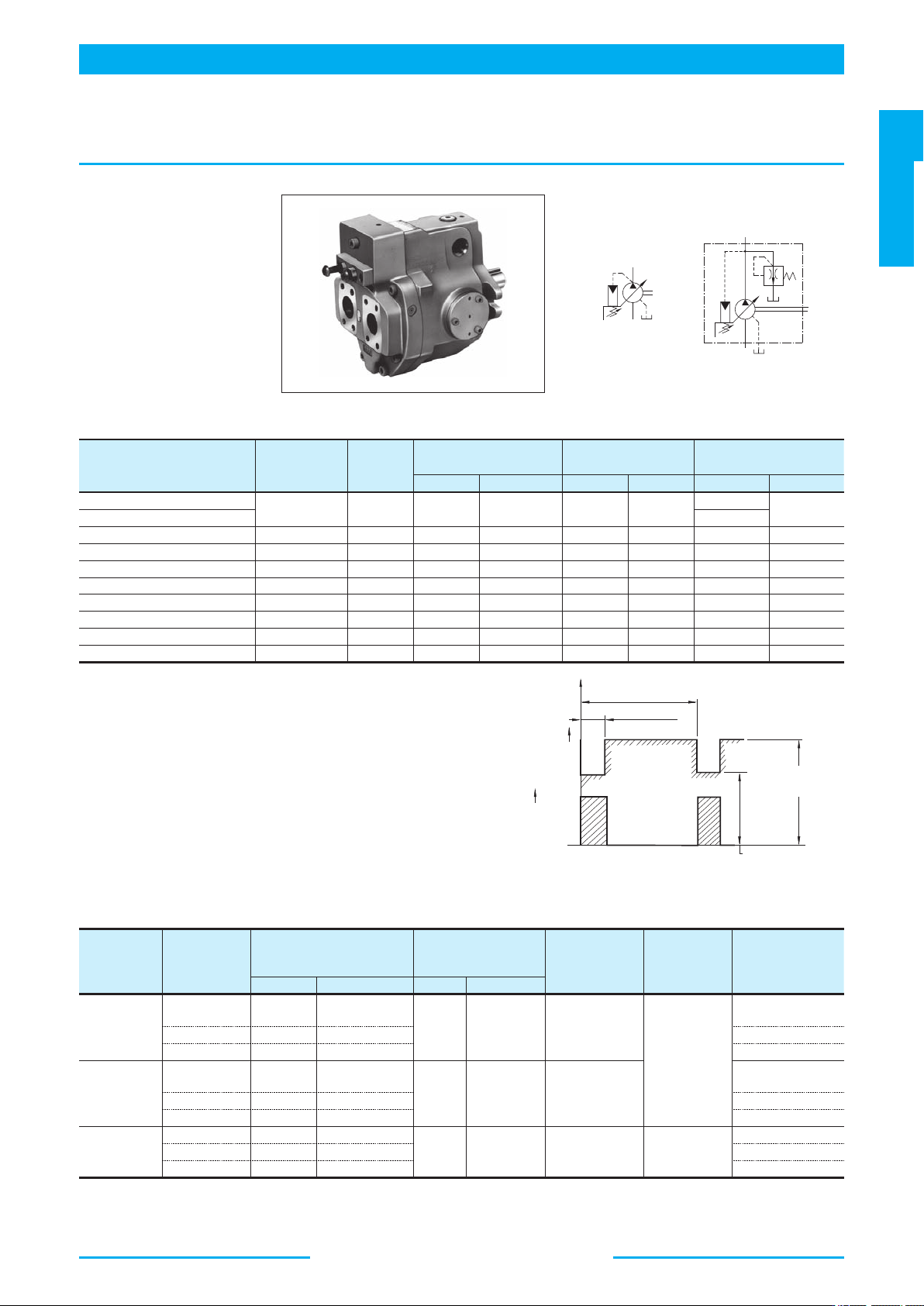
★1. Whenever setting pressure, make sure the full cut-off pressure never exceeds
the maximum intermittent pressure.
★2. Care should be taken in cases of used at a higher pressure than the rated
pressure, because operating terms may be restricted. For example, if used as
per maximum illustrated operating conditions, intermittent time at maximum
flow is restricted to under 1/5 of one cycle time and under six seconds
simultaneously. Conditions may vary according to the actual working pressure
and delivery (inclination angle of the swash plate). Consult factory or Yuken
sales representative for further information.
★3. Care should be taken in cases of used at a higher pressure than the rated
pressure, because operating terms may be restricted. For example, if used as
per maximum illustrated operating conditions, intermittent time at maximum
flow is restricted to under 1/5 of one cycle time and under six seconds
simultaneously. Conditions may vary according to the actual working pressure
and delivery (inclination angle of the swash plate). Consult factory or Yuken
sales representative for further information.
★1. The figures in brackets are for A22 type.
★2. As the specific gravities of water-glycol fluids and phosphate ester type fluids are higher than one, an overhead reservoir is required when pumps
are operated at 1400 r/min or more.
■ Specifications
Model Numbers
Geometric
Displacement
cm
3
/rev
Minimum
Adj. Flow
cm
3
/rev
Operating Pressure
MPa
Shaft Speed Range
r/min
Approx. Mass
kg
Rated
★2
Intermittent
★1
Max. Min. Flange Mtg. Foot Mtg.
A10-FR01B-12
10.0 2 16 21 1800 600
5.1
—
A10-FR01C/H-12 8.5
A16-
*
-R-01-
*
-
*
-K-32 15.8 4 16 21 1800 600 16.5 18.7
A22-
*
-R-01-
*
-
*
-K-32 22.2 6 16 16 1800 600 16.5 18.7
A37-
*
-R-01-
*
-
*
-K-32 36.9 10 16 21 1800 600 28.0 32.3
A56-
*
-R-01-
*
-
*
-K-32 56.2 12 16 21 1800 600 35.0 39.3
A70-
*
R01
*
S-60 70.0 36 25 28 1800 600 58.5 70.5
A90-
*
R01
*
S-60 91.0 56 25 28 1800 600 72.5 93
A100-
*
R01
*
S-10 100 62 21 21 1800 600 72.5 93
A145-
*
R01
*
S-60 145 83 25 28 1800 600 92.5 117.7
● Specifications and Design numbers for Special Fluids
Type of
Fluids
Pump
Series
Operating Pressure
MPa
Allowable Maximum
Shaft Speed
r/min
Temperature
Range
°C
Viscosity
Range
mm
2
/s
Design Numbers for
Special Fluid
Rated Intermittent Rated Max.
Water-
Glycols
A16-A56 14
16
(14)
★1
1200 (1800)
★2
0-50
20-200
3230
A70-A145 21 21 6030
A100 16 16 1030
Phosphate
Ester Type
A16-A56 14
16
(14)
★1
1200 (1800)
★2
0-60
3206
A70-A145 21 21 6006
A100 21 21 1006
Polyol
Ester Type
A16-A56 16 16
1800 1800 0-60 20-200
32450
A70-A145 21 21 60450
A100 21 21 10450
A
Series Variable Displacement Piston Pumps, Pressure Compensator Type
M
O
M
O
1.
*
1
*
1
*
0
1/5 of One Cycle
20 MPa
(27 MPa)
21 MPa
(28 MPa)
Max.
Pressure
Output
Flow
(Max. 6s)
One Cycle Time
Applicable only for "A70/90/145"
32
A
Series Variable Displacement Piston Pumps
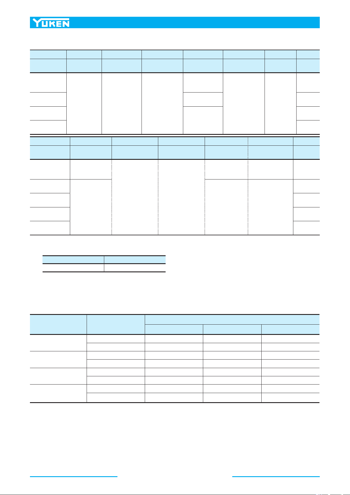
■ Model Number Designation
A16 -F -R -01 -B -S -K -32
Series Number Mounting
Direction of
Rotation
Control Type
Pres. Adj. Range
MPa
Port Position
Shaft
Extension
Design
Number
A16
(15.8 cm
3
/rev)
F: Flange
Mtg.
L: Foot
Mtg.
(
Viewed from
)
Shaft End
R: Clockwise
★2
(Normal)
01: Pressure
Compensator
Type
B: 1.2 - 7
C: 1.2 - 16
H: 1.2 - 21
None:
Axial Port
S:
Side Port
K:
Keyed Shaft
32
A22
(22.2 cm
3
/rev)
B: 1.2 - 7
C: 1.2 - 16
32
A37
(36.9 cm
3
/rev)
B: 1.2 - 7
C: 1.2 - 16
H: 1.2 - 21
32
A56
(56.2 cm
3
/rev)
32
A70 -F R 01 B S -60
Series Number Mounting
Direction of
Rotation
Control Type
Pres. Adj. Range
MPa
Port Position
Design
Number
A10
(10.0 cm
3
/rev)
F: Flange
★1
Mtg.
(
Viewed from
)
Shaft End
R: Clockwise
★2
(Normal)
01: Pressure
Compensator
Type
B: 1.2 - 7
C: 2.0 - 16
H: 2.0 - 21
—
12
A70
(70.0 cm
3
/rev)
F: Flange
Mtg.
L: Foot
Mtg.
B: 1.2 - 7
C: 1.5 - 16
H: 1.8 - 21
K: 2.0 - 28
S: Side Port
60
A90
(91.0 cm
3
/rev)
60
A100
(100 cm
3
/rev)
60
A145
(145 cm
3
/rev)
60
★ 1. When A10 pump is used as the foot Mtg., order the Mtg. Bracket kit shown below separately. Refer to page 20 for dimensions of the Mtg.
bracket.
Note: The mounting bracket kit consists of a mounting bracket, two hex. bolts and two plain washer.
Mtg. Bracket Kit Numbers Approx. Mass kg
LP-1A-10 2.2
★ 2. Available to supply pump with anti-clockwise rotation (Except A100). Consult Yuken for details.
■ Pipe Flange Kits
Pipe flange kits are available. When ordering, specify the kit number from the table below.
Pump Model Numbers Name of Port
Pipe Flange Kit Numbers
Threaded Connection Socket Welding
★
Butt Welding
A16
-
*
-
R
-
01
A22
-
*
-
R
-
01
Suction F5
-
06
-
A
-
10 F5
-
06
-
B
-
10 F5
-
06
-
C
-
10
Discharge F5
-
06
-
A
-
10 F5
-
06
-
B
-
10 F5
-
06
-
C
-
10
A37
-
*
-
R
-
01
A56
-
*
-
R
-
01
Suction F5
-
10
-
A
-
10 F5
-
10
-
B
-
10 F5
-
10
-
C
-
10
Discharge F5
-
10
-
A
-
10 F5
-
10
-
B
-
10 F5
-
10
-
C
-
10
A70
-
*R01
Suction F5
-
12
-
A
-
10 F5
-
12
-
B
-
10 F5
-
12
-
C
-
10
Discharge F5
-
08
-
A
-
10 F5
-
08
-
B
-
10 F5
-
08
-
C
-
10
A90
-
*R01
A100
-
*R01
A145
-
*R01
Suction F5
-
16
-
A
-
10 F5
-
16
-
B
-
10 F5
-
16
-
C
-
10
Discharge F5
-
10
-
A
-
10 F5
-
10
-
B
-
10 F5
-
10
-
C
-
10
★ In case of using socket welding flanges, there is a case where the operating pressure should be set lower than the normal because of strength of the
flanges. Therefore, please pay cautious attention to the operating pressure when the socket welding flanges are used.
● Details of the pipe flange kits are shown on page 262.