A16-F-R-00-H-S-K-A200-32408柱塞泵资料.pdf - 第50页
74 A Series V ariable Displacement Piston Pumps Electro-Hydraulic Propor tional Pressure & Flo w Control T ype ■ Outboard Pumps A37 to A145 type pumps, except A16/A22/A45, can be used as double pumps, by connecting a…
73
PISTON PUMPS
A Series
A
Series Variable Displacement Piston Pumps
Electro-Hydraulic Proportional Pressure & Flow Control Type
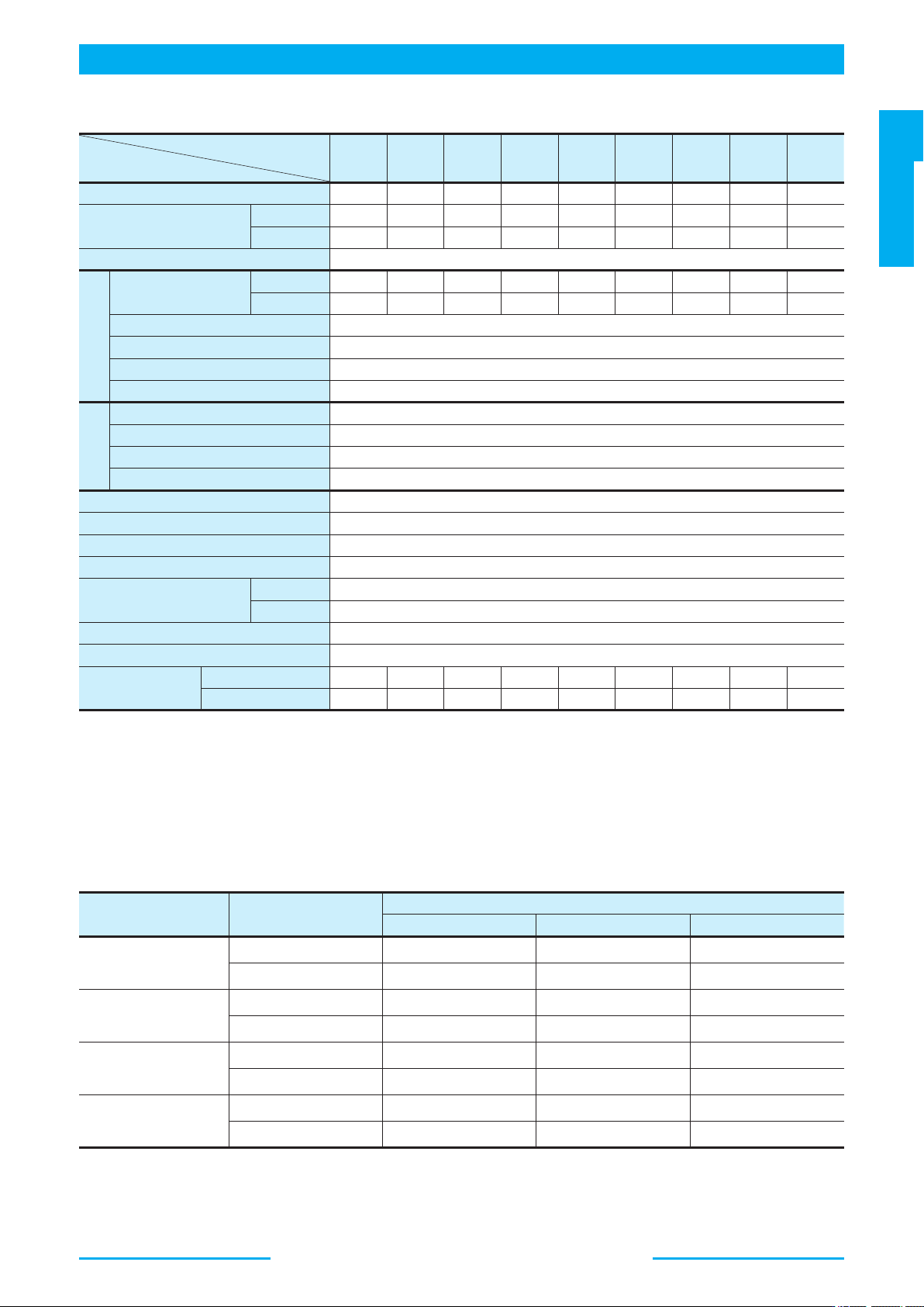
■ Specifications
★1. Whenever setting pressure, make sure the full cut-off pressure never exceeds the maximum intermittent pressure.
★2. When operating the pump exceeding the rated pressure, operating conditions are restricted.
Refer to page 31 for the details.
★3. Maximum flow differs to shaft speed.
The value listed above indicates shaft speed of 1800 r/min.
For other shaft speed calculate by the ratio of shaft speed.
■ Pipe Flange Kits
Pipe flange kits are available. When ordering, specify the kit number from the table below.
★ In case of using socket welding flanges, there is a case where the operating pressure should be set lower than the normal because of strength of the
flanges. Therefore, please pay cautious attention to the operating pressure when the socket welding flanges are used.
● Details of the pipe flange kits are shown on page 262.
Model Numbers
Descriptions
A16 A22 A37 A45 A56 A70 A90 A100 A145
Geometric Displacement cm
3
/rev 15.8 22.2 36.9 45.0 56.2 70.0 91.0 100 145
Operating Pressure MPa
Rated
★2
16 16 16 16 16 25 25 21 25
Intermittent
★1
21 16 21 17.2 21 28 28 21 28
Shaft Speed Range r/min 600 - 1800
Flow Control
Max. Flow
★3
L/min
50 Hz Pin 28.4 40.0 66.4 81.0 101 126 163 180 261
60 Hz Pin 23.7 33.3 55.4 67.0 84.3 105 136 150 217
Min. Pres. Required for Flow Adj. MPa 2
Hysteresis 1 % or less
Repeatability 1 % or less
Input Signal Max. Flow / 5 V DC
Pressure
Control
Min. Adjustment Pressure MPa 0.7
Hysteresis 1 % or less
Repeatability 1 % or less
Input Signal Specified Control Pressure / 5 V DC
Coil Resistance Ω(@20℃) 10
Input Impedance Flow Control : 10 kΩ Pressure Control : 10 kΩ
Supply Electric Power 24 V DC (21 - 28 V Included Ripple)
Power Input (Max.) W 30
Output Signal
Flow 5 V DC / Max. Flow (50 Hz Pin)
Pressure 5 V DC / Specified Control Pressure
Alarm Signal Output (Open Collector) Voltage : Max. 30 V DC Current : Max. 40 mA
Ambient Temperature ℃ 0 - 50 (With Circulated Air)
Approx. Mass kg
Flange Mtg. 20.5 20.5 32 32 39 64 76.5 76.5 96.4
Foot Mtg. 22.7 22.7 36.3 36.3 43.3 76 97 97 121.4
Pump Model Numbers Name of Port
Pipe Flange Kit Numbers
Threaded Connection Socket Welding
★
Butt Welding
A 16-*R04E
A 22-*R04E
Suction F5-06-A-10 F5-06-B-10 F5-06-C-10
Discharge F5-06-A-10 F5-06-B-10 F5-06-C-10
A 37-*R04E
A 45-*R04E
A 56-*R04E
Suction F5-10-A-10 F5-10-B-10 F5-10-C-10
Discharge F5-10-A-10 F5-10-B-10 F5-10-C-10
A 70-*R04E
Suction F5-12-A-10 F5-12-B-10 F5-12-C-10
Discharge F5-08-A-10 F5-08-B-10 F5-08-C-10
A 90-*R04E
A100-*R04E
A145-*R04E
Suction F5-16-A-10 F5-16-B-10 F5-16-C-10
Discharge F5-10-A-10 F5-10-B-10 F5-10-C-10
74
A
Series Variable Displacement Piston Pumps
Electro-Hydraulic Proportional Pressure & Flow Control Type
■ Outboard Pumps
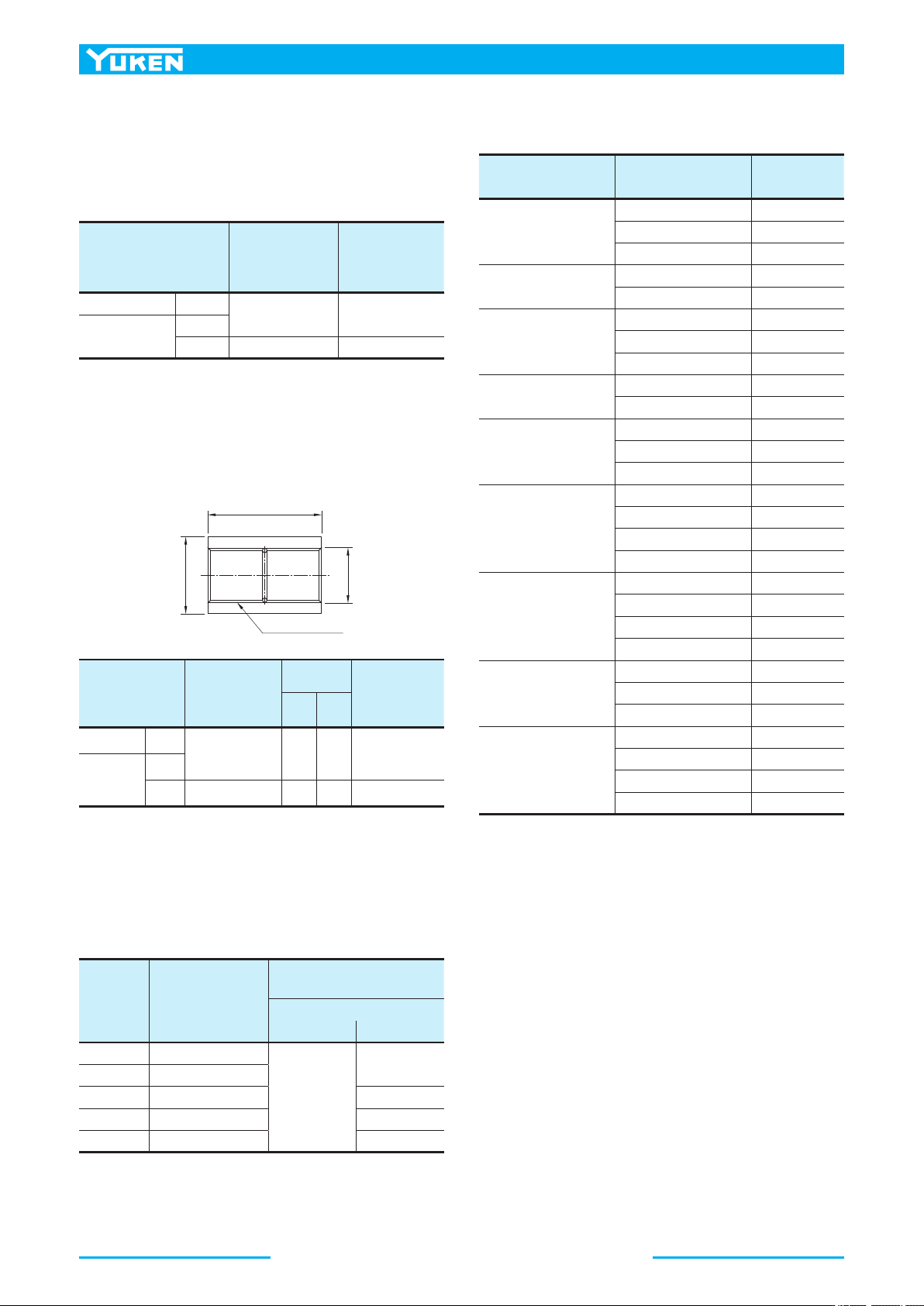
A37 to A145 type pumps, except A16/A22/A45, can be
used as double pumps, by connecting an outboard pump on
the cover side. See the table below for details.
● Connectable Outboard Pump
■ Attachment
● Amplifier
● Coupling
Please use assembly part number when ordering coupling
assemblies for shaft connections to outboard pumps.
● Selecting an Outboard Pump Type
The maximum torque of outboard pumps is limited by shaft
and coupling assembly strength. When determining the
outboard pump type, the value of the displacement times
the pressure for a particular pump should not exceed the
value shown in the table below.
★ Connectable pumps shafts are involute-serrated design, not the
standard parallel key slot design. For details, including pump
dimensions and model numbers, consult Yuken.
Note 1. The symbol "★", shown with pump and amplifier model
numbers, is the control pressure at input signal of 5 V.
2. Cable for pump-amplifier connection is not included. See Page
81 for details on ordering cables.
・q1, q2 : Displacement cm
3
/rev
・P1, P2 : Pressure MPa
・ For selection of the appropriate pump, both values, ① and ②, should
be satisfied.
"D1"Dia.
40mm
"D2"Dia.
Involute-serration
Pump Model Numbers
Amplifier Model
Numbers
Control Pressure
MPa
A16-*R04E★-06-42
SK1106-★-16-06-10 - 14.7
SK1106-★-16-06-1001 14.8 - 19.6
SK1106-★-16-06-1002 19.7 - 21.0
A22-*R04E★-11-42
SK1106-★-22-11-10 - 14.7
SK1106-★-22-11-1001 14.8 - 16.0
A37-*R04E★-60-42
SK1106-★-37-60-10 - 14.7
SK1106-★-37-60-1001 14.8 - 19.6
SK1106-★-37-60-1002 19.7 - 21.0
A45-*R04E★*-60-10
SK1106-★-45-60-10 - 14.7
SK1106-★-45-60-1001 14.8 - 17.2
A56-*R04E★-60-42
SK1106-★-56-60-10 - 14.7
SK1106-★-56-60-1001 14.8 - 19.6
SK1106-★-56-60-1002 19.7 - 21.0
A70-*R04E★*-60-60
SK1106-★-70-60-10 - 14.7
SK1106-★-70-60-1001 14.8 - 19.6
SK1106-★-70-60-1002 19.7 - 22.6
SK1106-★-70-60-1003 22.7 -
A90-*R04E★*-60-60
SK1106-★-91-60-10 - 14.7
SK1106-★-91-60-1001 14.8 - 19.6
SK1106-★-91-60-1002 19.7 - 22.6
SK1106-★-91-60-1003 22.7 -
A100-*R04E★-60-10
SK1106-★-100-60-10 - 14.7
SK1106-★-100-60-1001 14.8 - 19.6
SK1106-★-100-60-1002 19.7 - 21.0
A145-*R04E★*-60-60
SK1106-★-145-60-10 - 14.7
SK1106-★-145-60-1001 14.8 - 19.6
SK1106-★-145-60-1002 19.7 - 22.6
SK1106-★-145-60-1003 22.7 -
Outboard Pump
Connection Symbol
Spigot Diameter
for Connecting
an Outboard Pump
mm
Connectable
Pump
★
A37/A56
None
82.55 A16, A22, PV2R1
A70/A90/
A100/A145
“A”
“A”
101.6 A37, PV2R2
Outboard Pump
Connection Symbol
Part Number of
Coupling Ass'y
Dimensions
mm
Serration Size
(
Nominal Dia.×
)
No. of Teeth×
Mojule
"D
1
" "D
2
"
A37/A56
None
098-PK412588-6 27 19.5 18.75×24×0.75
A70/A90/
A100/A145
“A”
“B”
098-PK412623-1 36 26 25×24×1
Pump
Model
No.
①Inboard Pump and
Outboard Pump
(q
1
×P
1
)+(q
2
×P
2
)
②Outboard Pump
q
2
×P
2
Outboard pump connection symbol
"None"/"A" "B"
A37 900 and less
519 and less
——
A56 1742 and less
A70 2408 and less 935 and less
A90/A100 4348 and less 977 and less
A145 4739 and less 951 and less
■ Instructions
● Input Signal
The pump is on unload condition when the pump is
operated without input signal voltage.
● Electric Source
Always turn off electric source whenever the connector for
swash plate tilt angle sensor is removed.
●
Compensation of Pump Maximum Regulated Flow at Frequency
If the same maximum flow is required at 50 Hz or 60 Hz,
connect short plug in the amplifier to 60 Hz at the place
where supplied frequency is 60 Hz. At this condition,
maximum flow comes to the same value at 50 Hz.
If short plug is used at 60 Hz without making the change,
maximum flow increased in proportion to frequency.
75
PISTON PUMPS
A Series
A
Series Variable Displacement Piston Pumps
Electro-Hydraulic Proportional Pressure & Flow Control Type
●A37
●A22
●A90
●A100
●A45
●A145
●A70
●A56●A16
0
8
16
24
32
1 2 3 4 5
1800r/min
1500r/min
0
120
100
80
60
40
20
1 2 3 4 5
1800r/min
1500r/min
0
10
20
30
40
45
1 2 3 4 5
1800r/min
1500r/min
0
150
125
100
75
50
25
1 2 3 4 5
1800r/min
1500r/min
0
20
40
60
80
1 2 3 4 5
1800r/min
1500r/min
0
150
175
125
100
75
50
25
1 2 3 4 5
1800r/min
1500r/min
0
160
180
120
80
40
1 2 3 4 5
1800r/min
1500r/min
0
80
90
60
40
20
1 2 3 4 5
1800r/min
1500r/min
0
40
80
120
160
200
240
280
1 2 3 4 5
1800r/min
1500r/min
Input Signal VDC Input Signal VDC
Output Flow L/min
Output Flow L/min
Input Signal VDC Input Signal VDC
Output Flow L/min
Output Flow L/min
Input Signal VDC
Input Signal VDC
Output Flow L/min
Output Flow L/min
Input Signal VDC
Input Signal VDC
Input Signal VDC
Output Flow L/min
Output Flow L/min
Output Flow L/min
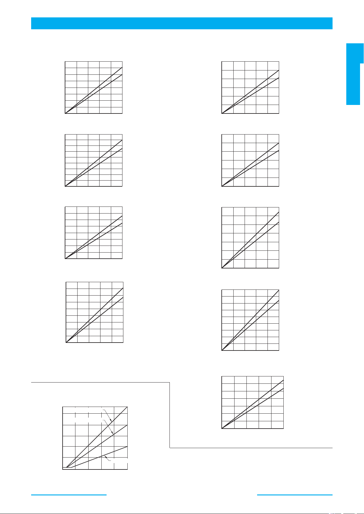
■ Full Cut-off Pres. vs. Input Signal
21
20
16
12
8
21MPa
16MPa
8MPa
4
0
1 2
3
4 5
Input Signal V
Full Cut-off Pressure MPa
Specified Pressure
A**
−
FR04E16M
A**
−
FR04E21M
A**
−
FR04E8M
■ Output Flow vs. Input Signal
Note: Pump characteristics at 1800 r/min is the same as those at
1500 r/min where frequency is compensated.
(Refer to page 74.)
Refer to page 35 to 42 for performance characteristics of pressure
compensator type excluding characteristics appeared on this catalogue.
As for A45, contact us for details.