A16-F-R-00-H-S-K-A200-32408柱塞泵资料.pdf - 第40页
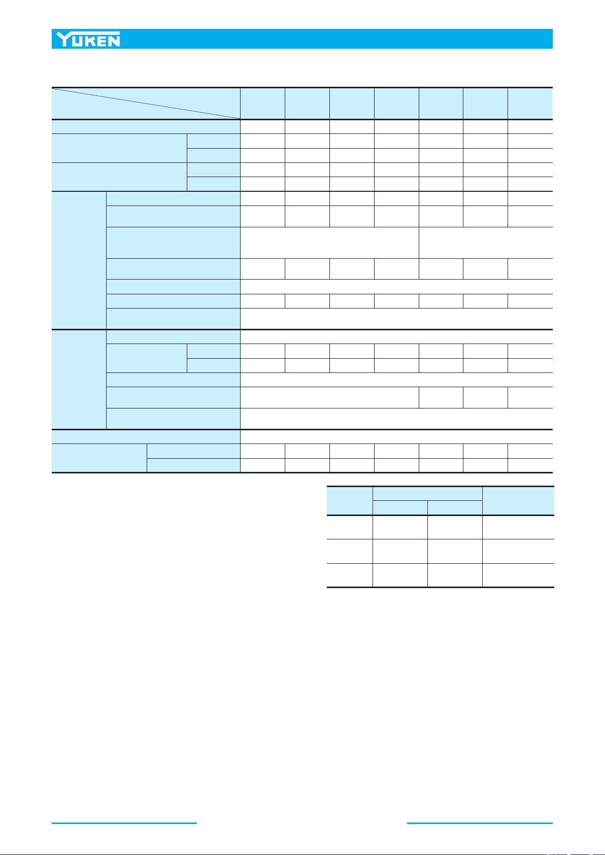
64 A Series V ariable Displacement Piston Pumps Propor tional Electro-Hydraulic Load Sensing T ype ■ Specifications ★ 1. Whenever setting pressure, make sure the full cut-off pressure never exceeds the maximum intermitte…
63
PISTON PUMPS
A Series
A
Series Variable Displacement Piston Pumps
Proportional Electro-Hydraulic Load Sensing Type
■ Pipe Flange Kits
Pipe flange kits are available. When ordering, specify the kit number from the table below.
★1. In case of using socket welding flanges, there is a case where the operating pressure should be set lower than the normal because of strength of
the flanges. Therefore, please pay cautious attension to the operating pressure when the socket welding flanges are used.
★2. Discharge port for pump model "A16" and "A22" is available only the threaded connections.
● Details of the pipe flange kits are shown on page 262.
Pump Model Numbers Name of Port
Pipe Flange Kit Numbers
Threaded Connection Socket Welding
★1
Butt Welding
A16-*-R-04
A22-*-R-04
Suction F5-06-A-10 F5-06-B-10 F5-06-C-10
Discharge —
★2
—
★2
—
★2
A37-*-R-04
A56-*-R-04
Suction F5-10-A-10 F5-10-B-10 F5-10-C-10
Discharge F5-06-A-10 F5-06-B-10 F5-06-C-10
A 70-*R04
Suction F5-12-A-10 F5-12-B-10 F5-12-C-10
Discharge F5-10-A-10 F5-10-B-10 F5-10-C-10
A 90-*R04
A145-*R04
Suction F5-16-A-10 F5-16-B-10 F5-16-C-10
Discharge F5-10-A-10 F5-10-B-10 F5-10-C-10
■ Instructions
● Bleeding Air
In order to get steadily controlled pressure and flow, bleed air by loosening the air vent screw and fill solenoid armature with
operating oil.
● Manual Adjustment Screws
Manual adjustment screws may be used for initial running adjustment or in case of electrical failures in order to adjust pressure
and flow temporarily. In case of normal use, put the manual adjustment screws back in their preset positions.
● Position of Cable Departure
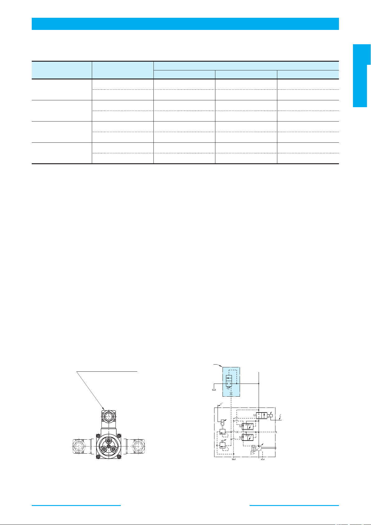
Position of cable departure can be changed. For details, refer to drawing below.
● Connection of Surge Cut-off Valve to "A" Series Pump (For A16 to A56 Type)
If using surge cut-off valve (SF1105-A-10), connect between pilot port "PP" of this pump and port "PP" of surge cut-off valve as
pilot piping (refer to symbol below).
Inside diameter of pipe should be more than 8 mm.
Consult Yuken of detail of surge cut-off valve.
M
O
i1
i2
"PP"
Surge Cut-off Valve
(SF1105-A-10)
Connector
(The direction can be altered
to every 90 degree angles.)
64
A
Series Variable Displacement Piston Pumps
Proportional Electro-Hydraulic Load Sensing Type
■ Specifications
★1. Whenever setting pressure, make sure the full cut-off pressure never
exceeds the maximum intermittent pressure.
★2. When operating the pump exceeding the rated pressure, operating
conditions are restricted. Refer to page 31 for the details.
★3. Specifications of power amplifiers, consult Yuken for details.
★4. The figure mentioned in the above table are those obtained using Yuken's
amplifier.
★5. Step response depends on circuit and operating conditions. Data shown in
the table above is an example based on the condition right.
Model Numbers
Descriptions
A16 A22 A37 A56 A70 A90 A145
Geometric Displacement cm
3
/rev 15.8 22.2 36.9 56.2 70.0 91.0 145
Operating Pressure MPa
Rated
★2
16 16 16 16 21 21 21
Intermittent
★1
21 16 21 21 21 21 21
Shaft Speed Range r/min
Max. 1800 1800 1800 1800 1800 1800 1800
Min. 600 600 600 600 600 600 600
Flow Control
Flow Adj. Range L/min 1 - 28.4 1 - 40 1 - 66 1 - 101 1 - 126 1 - 163 2 - 261
Min. Pres. Required
for Flow Adj.
MPa 1.5 1.5 1.5 2.0 1.0 1.0 1.0
Differential Pres.
(Discharge Pres.
-Load Pres.)
MPa 0.37 0.22
Step Response
★5
(0 → Max. Flow)
ms 70 80 120 125 100 120 210
Hysteresis 3 % or less
★1
Rated Current mA 900 700 740 790 820 920 920
Coil Resistance
(20°C)
10
Pres. Control
Pres. Adj. Range MPa Refer to Model Number Designation
Step Response ms
t
1
★5
80 80 50 55 150 150 160
t
2
★5
140 90 80 80 80 120 180
Hysteresis 2 % or less
★1
Rated Current mA
(Pres. Adj. Range)
B: 770, C:880, H:790
C: 860
H: 765
C: 873
H: 765
C: 875
H: 755
Coil Resistance
(20°C)
Ω 10
Applicable Amplifier Model
★3
AME-D2-1010-11
Approx. Mass kg
Flange Mtg. 32 32 38 45 72.5 88.5 109.5
Foot Mtg. 34.2 34.2 43.2 49.3 84.5 109 134.5
Model
Pres. Step Response
Loading Volume
t
1
t
2
A16, A22 1.5 → 16 MPa 16 → 1.5 MPa
High Pressure Hose
3/8" × 2 m
A37, A56 2.0 → 16 MPa 16 → 2.0 MPa
High Pressure Hose
3/4" × 2 m
A70, A90
A145
3.0 → 16 MPa 16 → 3.0 MPa
High Pressure Hose
1-1/4" × 2 m
65
PISTON PUMPS
A Series
A
Series Variable Displacement Piston Pumps
Proportional Electro-Hydraulic Load Sensing Type
"
H
"
"
C
"
"
B
"
21
20
16
12
8
4
0
Full Cut-off Pressure
MPa
200 400 600 800 900
Input Current
mA
"
H
"
"
C
"
Input Current
0
200 400 600 800
mA
1000
20
16
12
8
4
Full Cut-off Pressure
MPa
24
N=1800 r/min
200 400 600 800 1000
Input Current
mA
Output Flow
L/min
32
24
16
8
0
N=1800 r/min
200 400 600 800
Input Current
mA
Output Flow
L/min
40
30
20
10
0
N=1800 r/min
200 400 600 800
Input Current
mA
Output Flow
L/min
70
60
50
40
30
20
10
0
N=1800 r/min
200 400 600 800
Input Current
mA
900
Output Flow
L/min
110
100
80
60
40
20
0
200 400 600 800
Input Current
mA
1000
N=1800 r/min
Output Flow
L/min
140
120
80
40
0
200 400 600 800
Input Current
mA
1000
Output Flow
L/min
200
160
120
80
40
0
200 400 600 800
Input Current
mA
1000
N=1800 r/min
N=1800 r/min
Output Flow
L/min
280
240
200
160
120
80
40
0
●A16/A22/A37/A56 ●A70/A90/A145
Note: Pressure adjustment range "H" is not available for A22.
●A16
●A22
●A37
●A56
●A70
●A90
●A145
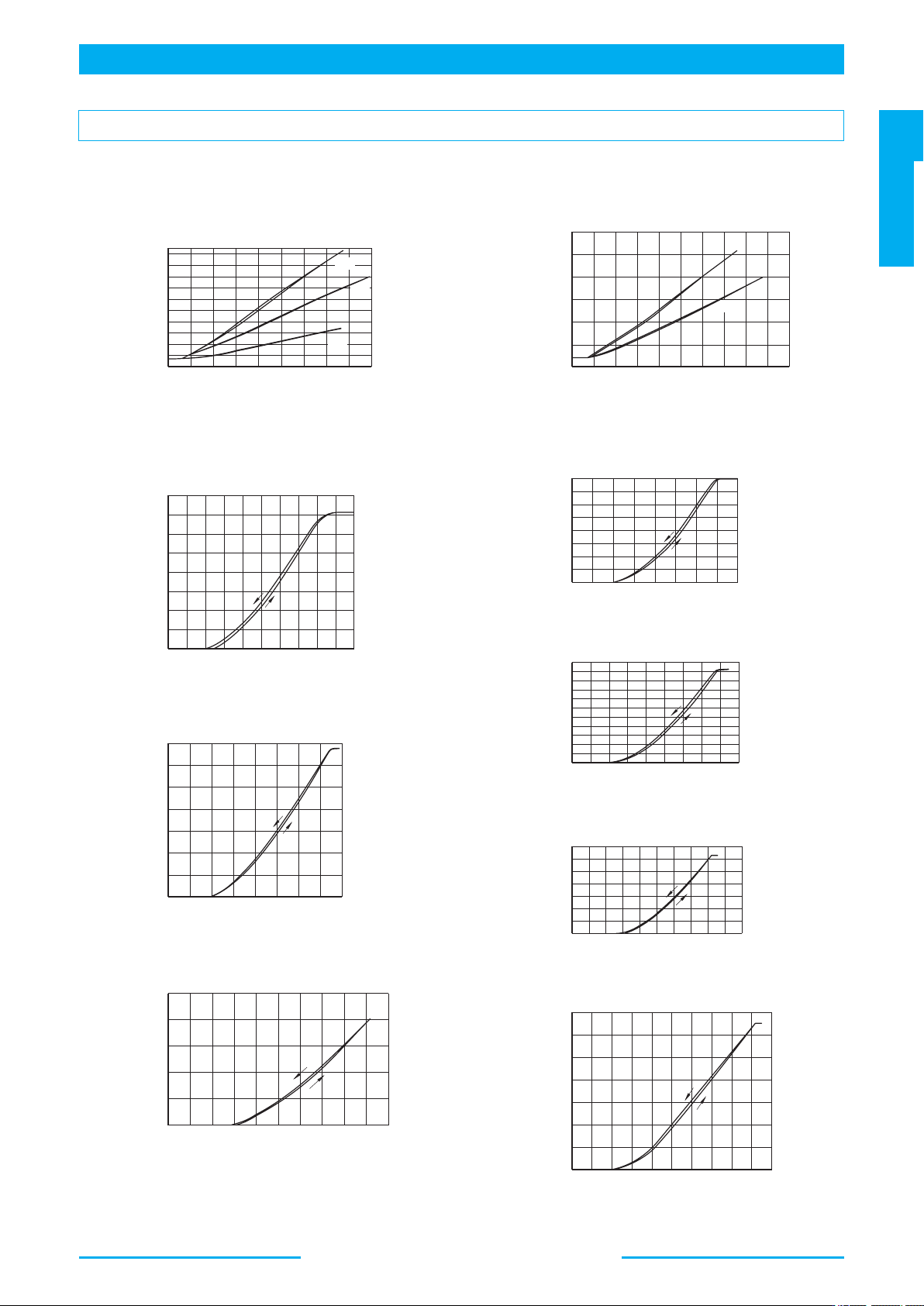
Typical Performance Characteristics at Viscosity 20 mm
2
/s [ISO VG32 Oils, 50°C]
■ Output Flow vs. Input Current
■ Full Cut-off Pres. vs. Input Signal