KE-2030使用说明书.pdf - 第35页
1 − 26 1.2.3 Component feeder Totally f our component f eeder bank s are pr ovided: two banks located at t he fr ont and rear of the PW B transport unit, respect ively. T he component supply method varies depending on th…
1 − 25
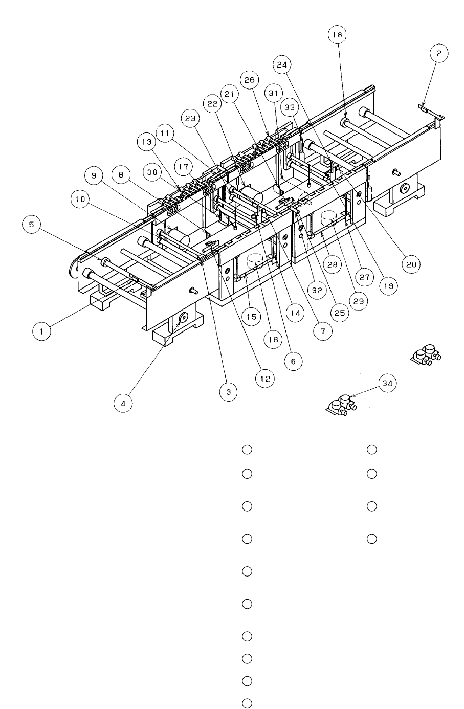
①
IN sensor
⑪
Stopper at the entrance
21
BU sensor at the exit
31
YC motor
②
OUT sensor
⑫
X pusher at the
entrance (Edge
reference option)
22
Center motor at the exit
32
C. board chuck cylinder
③
Wait sensor
⑬
Y pusher at the
entrance (Edge
reference option)
23
Drive shaft (at the exit)
33
S. board chuck cylinder
④
IN motor
⑭
Centering pin at the
entrance
24
Stopper at the exit
34
Depressure valve
(Edge reference
option)
⑤
Drive shaft (IN)
⑮
BU table at the
entrance
25
X pusher at the exit
(Edge reference
option)
⑥
Stop sensor at the
entrance
⑯
BU motor at the
entrance
26
Y pusher at the exit
(Edge reference
option)
⑦
C.OUT sensor at the
entrance
⑰
BU pin
27
Centering pin at the
exit
⑧
BU sensor at the
entrance
⑱
Drive shaft (OUT)
28
BU table at the exit
⑨
Center motor at the
entrance
⑲
Stop sensor at the exit
29
BU motor at the exit
⑩
Drive shaft
(at the entrance)
⑳
C.OUT sensor at the
exit
30
YC origin sensor/+ limit
sensor/- limit sensor
1 − 26
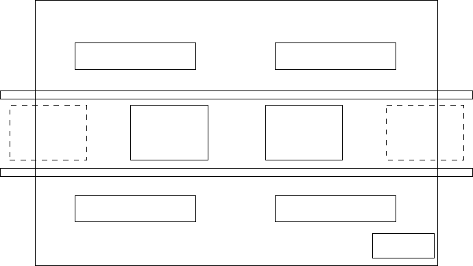
1.2.3 Component feeder
Totally four component feeder banks are provided: two banks located at the front
and rear of the PWB transport unit, respectively. The component supply method
varies depending on the package style of components: tape , stick or bulk.
Tapes are fed from the tape feeder, sticks are from the stick feeder, and bulks are
from the bulk feeder respectively, and all types of feeders are mounted on the feeder
banks to feed each type of components.
When using the changer table (option), the feeder bank can be removed from the
main unit of this machine for preparation.
Figure 1.2.3.1
Feeder banks Feeder banks
PWB PWB
Feeder banks Feeder banks
Monitor
1 − 27
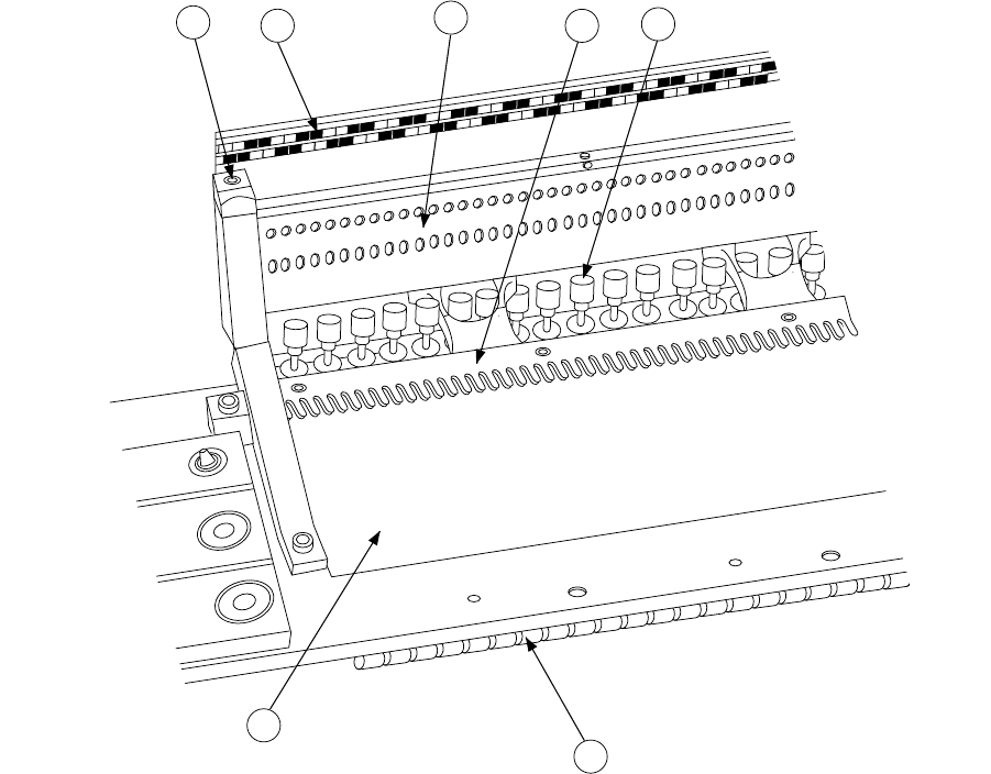
1. Feeder bank parts identification (See Figure 1.2.3.2.)
The tape feeder loaded with taped components and stick feeder loaded with
components in sticks are positioned and secured by the fixing plate
⑦
, fixing
plate B e, and lock shaft
④
.
The tape feeder is driven by the drive cylinders
⑤
.
The position label
⑥
is used to determine the position at which each feeder is
installed. You can see LED status of the FPI (optional) to decide where to set
each feeder.
The bank mark u is the mark for correcting the position of the feeder set.
6
2
4
1
5
7
3
①
Feeder bank
⑤
Drive cylinder
②
Fixing plate
⑥
Position label
③
Fixing plate B
⑦
Bank mark
④
Lock shaft
Figure 1.2.3.2