00198574-01_Process_Foundation_DEK_Micron_EN.pdf - 第30页
5 Product File and Machine Setup 5.2 Create a New Product File 30 Process Foundation DEK Micron-Series 12/2017 5.2 Create a New Product File Creating a New Product File From an Existing File This is often the quickest wa…
5 Product File and Machine Setup
5.1 Program Basic Machine Set up Parameters
Process Foundation DEK Micron-Series 12/2017 29
5 Product File and Machine Setup
5.1 Program Basic Machine Set up Parameters
The DEK printer can be configured to operate in a number of different modes depending on the
application and the options that have been added to the printer.
The machine set up parameters should be configured prior to setting up the product file and a new
process. The table below lists some of the most basic and important parameters.
Exercise
Which main menu do these parameters appear in?
__________________________________________
Complete the table below by recording the options available and indicating the most likely
configuration for your production environment.
Machine Set up Parameter Definition
Print Mode
Transport Mode
Upline/ Downline Protocol
Tooling Hardware
Consumable Action
Cleaner Model
Fiducial Reference
Screen Size

5 Product File and Machine Setup
5.2 Create a New Product File
30 Process Foundation DEK Micron-Series 12/2017
5.2 Create a New Product File
Creating a New Product File From an Existing File
This is often the quickest way to get started. It is the most efficient method if the new product has
similarities in size, process or vision inspection to an existing one. There are however, precautions
to remember: always zero any offsets from the old file and never assume that the under-screen
cleaner is transferable - this should always be confirmed through test and observation.
Copying Vision inspection Data
If your machine is configured with a vision inspection package and it has been enabled in the
machine set up menu you will be given the opportunity to copy all or some of the set up parameters
from the existing file to the new one.
Creating a Product File From the Default File
All machines are shipped with a DEFAULT.PR1 file loaded. This may be used as the basis for a
new file. However, the parameter settings are not based on any typical process so each parameter
will need to be reviewed and probably modified.
Customizing the Default File
It is a good idea to create one or more default files that approximate to a good set-up for your own
product range. For instance a file named GSM.PR1 could be used for all mobile phones,
Mother.PR1 could be used for motherboards, etc. When the message "Do you also want to create
a copy of the inspection file?" is displayed whilst creating a new file name, choose the option
"Globals only".
Product Identification
The product ID field allows you to add some useful information to the product file in addition to its
name. For instance you may wish to identify the stencil image number, paste type, squeegee
length, ECM set point, etc. and this may reduce the potential for operator error during set-up.
Minimum Product File Parameters
There are five pieces of information required for the most basic product file setup. These
are:
●
Substrate width (note: think of this as the rail width)
●
Substrate length
●
Substrate thickness
●
The coordinates of the first fiducial
●
The coordinates of the second fiducial
5 Product File and Machine Setup
5.2 Create a New Product File
Process Foundation DEK Micron-Series 12/2017 31
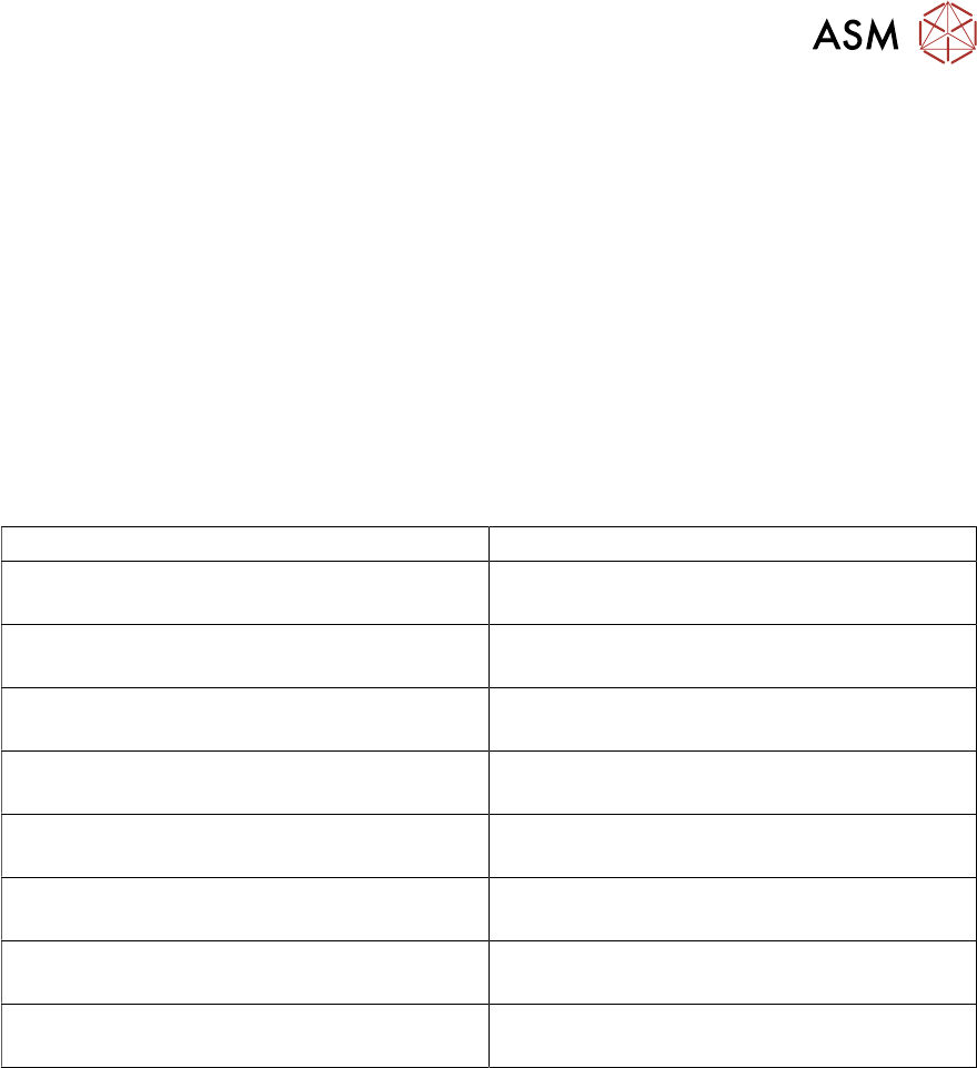
Importance of Accurate Board Width
The DEK printer has an automatic allowance of 0.2mm extra in the width to compensate for board
variations. Adding to this will decrease the effectiveness of the edge clamps and may lead to
misalignment of the printed image. An example demonstrating the effect of increasing the rail width
by just 0.5mm has on Y-axis alignment repeatability can be seen below.
Rail width parameter set to 250mm Rail width parameter set to 250.5mm
SPC graphs showing Post print "Y" alignment repeatability on a DEK06 test board.
Keep rail width as tight as practically possible!
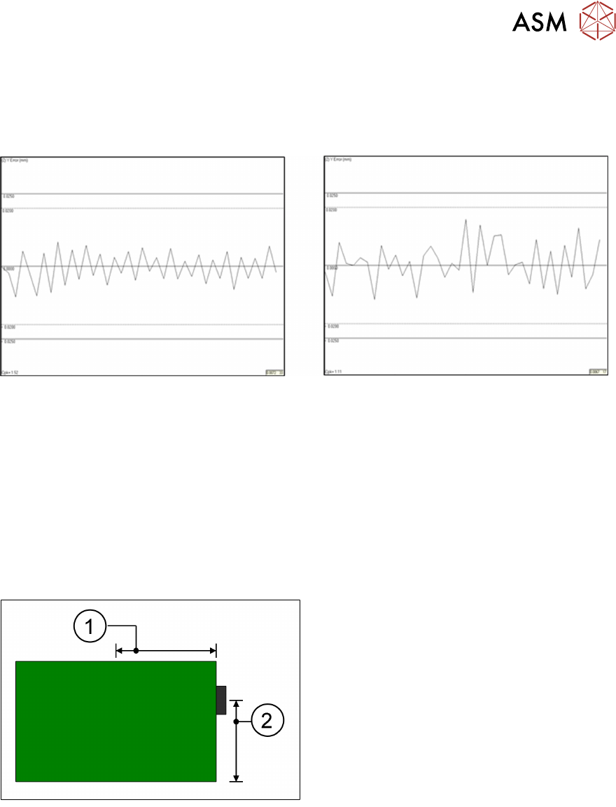
Board Stop Position
The board stop is a mechanical bracket that is mounted on the camera assembly. It is driven
down between the rails as the board travels along the transport belts and stops the board in the
area of the stencil image.
Its default position is X = 0.5 x board length*, Y = 0.66 x board width*. These coordinates can be
adjusted in the edit page. Note, however, that if any board dimension is later adjusted, the board
stop will automatically revert back to the default position!
1. Board Stop X
2. Board Stop Y
The board stop position could be adjusted, for instance to avoid cut out sections or to place the
stop closer to the rails to stop large or warped boards from slipping underneath.
Which Fiducial First?
Unless you are using the remote board stop option, the cycle time of the printer can be optimised
by making sure the first fiducial is the rightmost fiducial. This is because the camera holds the
standard board stop, which will always be on the right edge of the PCB. So putting the first fiducial
closer to the right will reduce the time it takes to travel around the fiducials. The bigger the
substrate: the greater the time saving. The following diagram indicates how to measure the fiducial
positions: