00198574-01_Process_Foundation_DEK_Micron_EN.pdf - 第48页
7 Product File and Machine Optimisation 7.2 Design an Under Screen Cleaning Strategy 48 Process Foundation DEK Micron-Series 12/2017 Exercise Using the method above, design a screen cleaning strategy that maintains print…

7 Product File and Machine Optimisation
7.2 Design an Under Screen Cleaning Strategy
Process Foundation DEK Micron-Series 12/2017 47
7.2 Design an Under Screen Cleaning Strategy
USC Performance
It is important that the under-screen cleaner is fully functional and optimised prior to attempting to
design a cleaning strategy. The methods of achieving this are described in the process
maintenance unit of this workbook.
Why Clean? When to Clean?
Cleaning the under side of the stencil keeps the process in control and reduces end of line defects.
It does, however, have a cost in terms of reduced throughput and consumable consumption. It is
very important, therefore, that the cleaner is optimised to give an effective clean only when
required. The cleaner can also be programmed to clean after a knead operation or after a set
period of downtime.
Cleaning Options
A flexible programming system allows the user to choose between dry, wet (solvent) and vacuum
cycles. For extra optimisation, it is possible to use two independent cleaning modes (Mode 1 and
Mode 2). For instance: a small regular cleaning cycle (i.e. a single dry) may be complemented by a
less frequent but more comprehensive clean (i.e. wet, vacuum, dry). In order to prevent cleaning
frequencies becoming erratic, Mode 1 and Mode 2 should be multiples of each other: i.e. Mode 2
every 5 prints and Mode 1 every 25 prints.
Paste Volume Recovery After Clean
When a clean stencil is first used, it may take two or three prints before the apertures are
sufficiently lubricated to enable effective release of the solder paste. A natural part of the printing
process, therefore, is to run with some element of aperture blockage (perhaps 20% or so, possibly
more with µBGA or other small apertures). A possible disadvantage of using a vacuum under-
screen cleaner is that removing this residue may alter the process for the subsequent one or two
prints.
Designing a Cleaning Strategy
One possible method for determining the best cleaning strategy is as follows:
1. Set up the product with the best print alignment possible – even a small offset can cause large
increases in USC frequency
2. Starting with a clean stencil, run production with the cleaner disabled. Inspect every board and
look for signs of printing defects. Note how many prints are possible before problems start
occurring. Check also the underside of the stencil every ten boards to see if it is getting too
dirty
3. Repeat the previous two steps two more times
4. Once the frequency of defects is established, program the USC to clean one or two boards
before this point to allow a safety margin. Introduce cleaning modes individually until all
defects are eliminated
5. The choice of cleaning programs will be determined by the type of defect observed: stencil
smearing or bridging may require a dry or wet and dry; stencil blockage or insufficient paste
may require a combination of wet, vacuum and dry; solder balling proven to be caused by
solder paste left on the underside of the stencil may need a more intensive program
Note: These recommendations are general and will be determined by the type of material used
– experimentation is vital.
6. If using a wet program, check the printed boards after a clean cycle to ensure there is no
solvent contamination
7. Monitor production and be prepared to make minor changes. Variations in temperature or
solder paste may cause new problems or amplify existing ones. Set the cleaner for worst-
case scenario
7 Product File and Machine Optimisation
7.2 Design an Under Screen Cleaning Strategy
48 Process Foundation DEK Micron-Series 12/2017
Exercise
Using the method above, design a screen cleaning strategy that maintains print volume and
prevents defects (paste bridging, solder balls, etc.) during an extended production run of a
minimum of 40 continuous prints.
Note: Ensure that the solvent and paper are primed before starting this experiment.
Parameter Value Comments
Screen Clean Mode 1
Screen Clean Rate 1
Screen Clean Mode 2
Screen Clean Rate 2
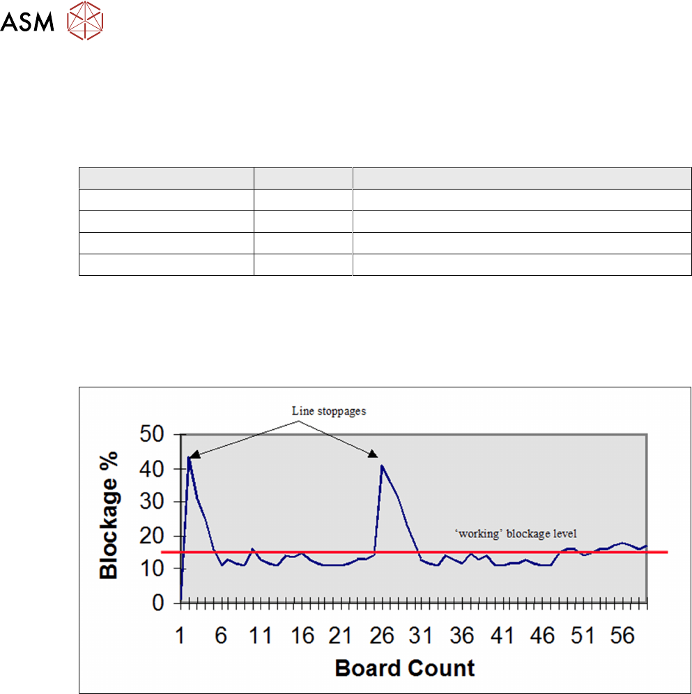
Effect of Line Stoppage on Process
Whenever the printer stops, the viscosity of the material will start to increase. This also applies to
material in the apertures that will dry faster than the main mass.
The graph below demonstrates the rapid rise in blockage after a downtime, and the recovery period
of several boards before the blockage returns to its normal, working level.
Clean After Downtime Strategy
It is sensible to clean paste from the stencil before a prolonged stoppage. However, this cannot
always be predicted so it is advisable to enable the Clean After Downtime options. There are two
parameters to consider:
Clean After Downtime: A specific cleaning program for downtime – since the objective is to
prevent dry paste sticking on the stencil and in the apertures, W/V/D would be a common choice of
program.
Clean After: The number of minutes after a stoppage at which the clean will occur. The value will
be determined by the paste characteristics and stencil design. The value should be as long as
possible to prevent unnecessary cleans. Five minutes to half an hour would be typical, but this
should be established through experimentation. Process stability will be most difficult to maintain
around fine pitch apertures, so these areas should be considered first when determining the
cleaning strategy.

7 Product File and Machine Optimisation
7.2 Design an Under Screen Cleaning Strategy
Process Foundation DEK Micron-Series 12/2017 49
Exercise
Discuss with your instructor the merits of using a downtime strategy in your current production
environment. Consider the paste characteristics, stencil design, and the frequency and duration of
line stoppages. Using this information estimate likely values for the parameters below:
Clean After Downtime ………………………………
Clean After ………………………………