Printer 710_810 v8 Adjustable Screen Mount.pdf - 第14页
ADJUSTA BLE SCREE N MOUNT (ASM) REP LAC EMEN T PR OCED URE S 12.14 Technical Reference Manual Chapter Issue 7 Oct 06 4. At the r ear web assemb ly , tighten t he two ho rizontal chase rail securing bolts until the outer …
ADJUSTABLE SCREEN MOUNT (ASM)
REPLACEMENT PROCEDURES
Chapter Issue 7 Oct 06 Technical Reference Manual 12.13
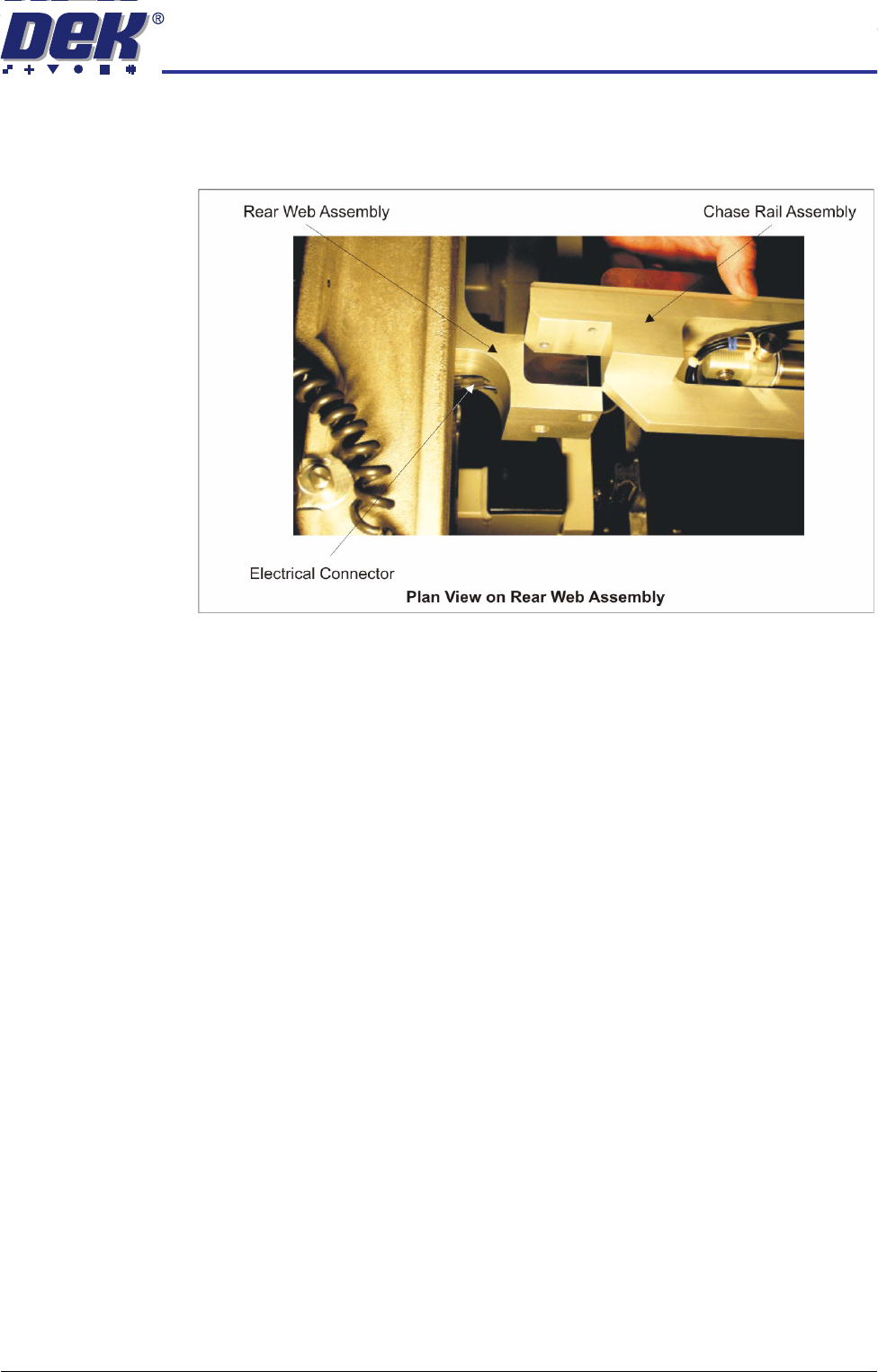
12. Lift the rear end of the chase rail assembly clear of the rear web assembly.
Carefully feed the electrical connector and pneumatic pipe through the
access hole in the rear web assembly.
13. Replace the chase rail assembly onto the rear web assembly ensuring the
electrical cable and pneumatic pipe are not trapped.
14. From the front of the machine carefully lift out the chase rail assembly
ensuring the electrical cable and pneumatic pipe does not snag on any part
of the machine.
Fitment 1. Carefully place the chase rail assembly onto the front and rear web assem-
blies from the front of the machine, ensuring the pneumatic pipes and
electrical cables are not trapped under the chase rail assemblies.
2. At the rear web assembly, lift the end of the chase rail assembly and first,
thread the electrical cable and subsequently the pneumatic pipe through the
access hole in the web.
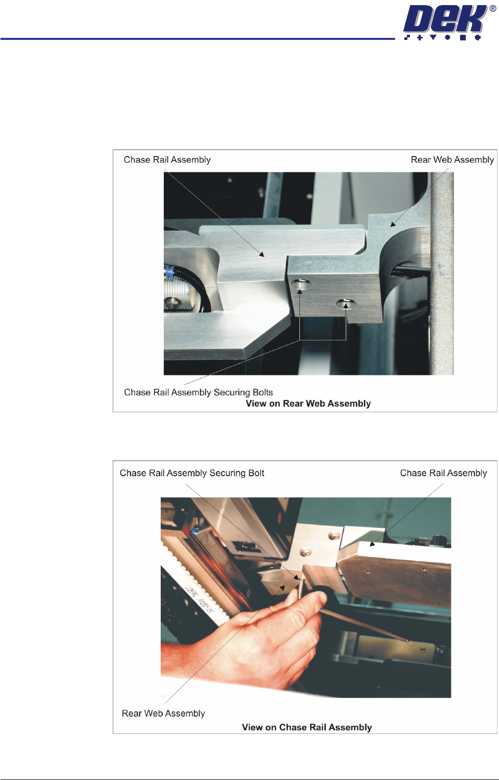
3. Loosely assemble the chase rail securing bolts (in seven positions) to the
front and rear web assemblies.
ADJUSTABLE SCREEN MOUNT (ASM)
REPLACEMENT PROCEDURES
12.14 Technical Reference Manual Chapter Issue 7 Oct 06
4. At the rear web assembly, tighten the two horizontal chase rail securing bolts
until the outer face of the chase rail just touches the web face.
CAUTION
SECURING BOLTS.
The two rear web horizontal chase rail securing bolts
must not be fully tighten at this juncture otherwise, damage to the
machine may occur.
5. Fully tighten the vertical chase rail securing bolt and subsequently complete
the tightening of the two horizontal rear chase rail securing bolts.
ADJUSTABLE SCREEN MOUNT (ASM)
REPLACEMENT PROCEDURES
Chapter Issue 7 Oct 06 Technical Reference Manual 12.15
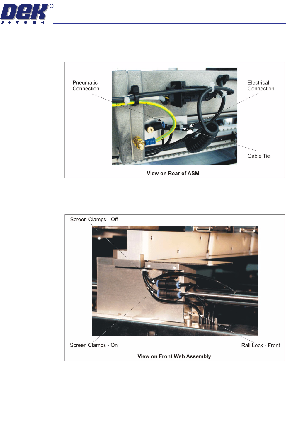
6. Route the pneumatic supply pipe and electrical cable to the rear web
connections. Fit the loom and pipe to the appropriate connectors and
secure the electrical loom with a cable tie.
7. At the front web assembly, fully tighten the four chase rail securing bolts.
8. Connect the Screen Clamps - Off and Screen Clamps - On pneumatic
pipes to the quick release pneumatic connections shown below.