0197787-01_UM_HeadVerification_708_EN.pdf - 第10页
SIPLACE Head V erification User Manual Edition 01/2015 10 2.2.3 Selection of Measurements Figure 3: Sele ction of measurem ents using exam ple of CP P The "Selection of Measurem ents" shows all head verificatio…
SIPLACE Head Verification
User Manual Edition 01/2015
9
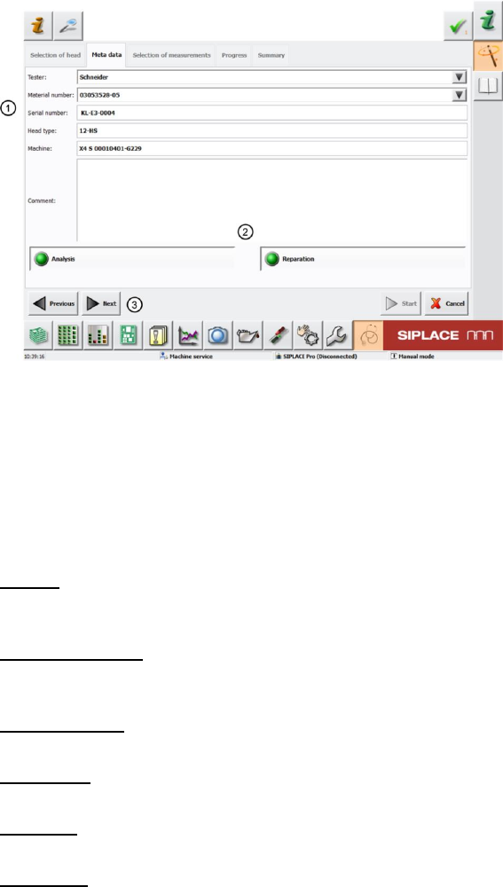
2.2.2 Meta Data
Figure 2: Meta Data
The following head data needs to be entered here so that the measurement is correctly recorded and
a results log with all required data about the head measured can be generated after the measurement.
If this check is conducted before head maintenance, the results log can be supplied with the head to
help the service personnel prepare the necessary steps and directly work on/replace the head parts
affected.
Please enter the following information here (1):
Tester:
Name the person performing head verification. All previous testers can be selected from the scroll-
down menu (black arrow).
Material number:
The material number of the head to be measured is read out of the EEPROM. All previous material
numbers can be selected from the scroll-down menu.
Serial number:
The serial number is automatically read out of the EEPROM.
Head type:
This is automatically entered, based on your selection of the head type (chapter 4.2.1)
Machine:
The machine number stored in the machine data is automatically entered here.
Comment:
The tester can enter comments about the measurement here, to help document the head
verification.
The two menu items "Analysis" and "Reparation" (2) remain selected.
Now click "Next" (3) to access the next menu item "Selection of measurements".
SIPLACE Head Verification
User Manual Edition 01/2015
10
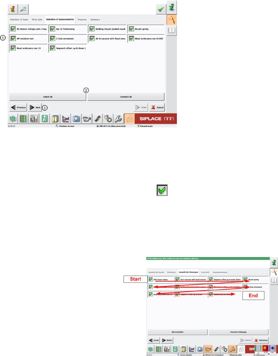
2.2.3 Selection of Measurements
Figure 3: Selection of measurements using example of CPP
The "Selection of Measurements" shows all head verification measurements which are possible for the
previously selected head type.
Our example shows all possible measurements for a CPP head.
The "Selection of Measurements" menu provides an overview of all individual measurements (1).
The green tick marks those which have been enabled.
Individual measurements can be selected separately by ticking or unticking.
You can also enable or disable all measurements at once with the following buttons (2)
"Select all" all measurements enabled or "Deselect all" all measurements disabled.
All measurements are enabled as a default!
In general, we recommend performing a complete head verification with all measurements as this is
the only way to gain a reliable conclusion about the overall state of the head.
The measurements are then conducted
"row for row” from top left to bottom right.
Then click "Next" (3),
SIPLACE Head Verification
User Manual Edition 01/2015
11
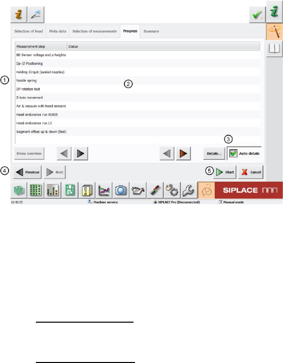
2.2.4 Overview of Measurements - Progress
Figure 4: Overview of measurements and progress
The following information is shown in the "Progress" menu:
1. All selected measurements are shown at "Measurement Step".
2. The "Status" shows the progress of any measurement currently being performed. If the
measurement has been completed you will see a "green tick for OK" or a "red cross for NOK"!
3. The "Auto details" button is enabled as a default
"Auto details" enabled
The GUI always shows the current measurement as soon as new measurement values
have been found.
"Auto details" disabled
During an ongoing measurement, you can use the arrow keys (black/red) to navigate
through completed measurements, while the current measurement is performed in the
background.
4. The "Previous" button switches over to the previous menu "Selection of Measurements" so
that you can make a new selection.
5. Click the "Start" button (5) to start the measurement and the software will change to the
"Measurement Step“ "Component sensor voltage and Z heights" (in our example)