0197787-01_UM_HeadVerification_708_EN.pdf - 第65页
SIPLACE Head V erification User Manual Edition 01/2015 65 One way of resolv ing the problem would be to check the nozzle for corr ect seat. As an exam ple, segment 4 (3) s hows that the "Measur e 1 [µm]" value …
SIPLACE Head Verification
User Manual Edition 01/2015
64
4.11.3 Explanation of Measurement Results Using Results PDF
These results can be seen if you scroll down the "Summary" menu or generate a results PDF!
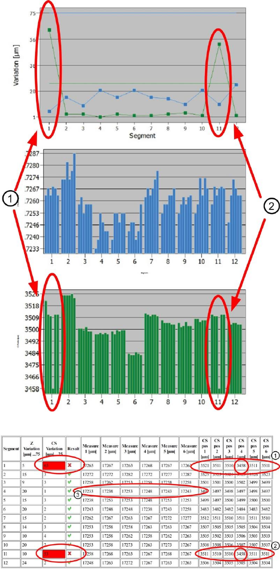
Figure 43: Results PDF DP-Z positioning_1
Figure 44: Results PDF DP-Z positioning_2
You can see that, in the case of segment 1 (1) and also segment 11 (2), the component sensor CS
pos 4 [µm] switches earlier at an angle of 180°. This is shown in the green bar chart.
This low value also means that the "CS Variation [µm]" value is outside the permitted tolerance.
Reliable placement of the entire DP positioning area can therefore not be guaranteed.

SIPLACE Head Verification
User Manual Edition 01/2015
65
One way of resolving the problem would be to check the nozzle for correct seat.
As an example, segment 4 (3) shows that the "Measure 1 [µm]" value for the Z-down light barrier at a
DP angle of 0° switches slightly earlier than at other angles.
In this case, the light barriers at segment 4 need to be cleaned through the service gap and the
switching ring may also need cleaning!
4.11.4 Meaning of the Results
"Z Variation [µm]" and "CS Variation [µm]" errors at all segments:
1. Mechanical damage to Z axis linear guide Replace Z drive
2. Z axis read unit dirty Clean Z read unit
"Z Variation [µm]" errors at individual segments:
1. Linear guide for segment damaged Replace linear guide for segment
2. Check Z-down light barrier for segment Clean the LB and switching ring through service
gap
"CS Variation [µm]" errors at individual segments:
1. Component sensor dirty Clean the lens
2. Component sensor dirty Replace component sensor
"CS Variation [µm]" errors at individual segments:
1. Linear guide for segment damaged Replace linear guide for segment
2. Bad nozzle seat Check the nozzle interface
3. Bad nozzle seat Replace nozzle
4.12 "DP Rotation Test" Measurement
The following tools are required for these measurements:
CPP: 12x nozzle type 2057 03070280-01 (calibration nozzle)
CP20P: 20x nozzle type 4235 03098748-01 (calibration nozzle)
CP20A: 20x nozzle type 1235 03015222-01 (calibration nozzle)
1x calibration component CPP 03010565-01
or
1x calibration component C&P20A/P 03034148-01
4.12.1 Explanation of Measurement – Procedure
The "DP rotation test" measurement determines how reliably a DP reaches the specified angle.
For this, the calibration component is picked up with the nozzle.
Then the calibration component is moved under the component camera and positioned by 4° (4000°)
with the DP.
After reaching the end position signal, the component camera is used to evaluate the calibration
component structure and to establish the actual rotation of the calibration component.
The measured rotary angle of the calibration component should now be within the permitted angle
tolerance. If this tolerance is undershot or exceeded, this indicates that this DP has a problem with
positioning the rotary angle.
The results of these measurements provide feedback about the following sources of errors:
1. Positioning accuracy of DP axis for segment
SIPLACE Head Verification
User Manual Edition 01/2015
66
Measurement steps:
Calibration nozzles are present at the segments
1. Head is moved over calibration component bag.
2. Segment 1 picks up calibration component.
3. Segment 1 is rotated by the star to the component camera.
4. Component camera determines the position and angle of the calibration component on the
nozzle
5. Segment 1 is rotated by 4° (4000°)
6. Component camera determines the position and angle of the calibration component on the
nozzle
7. The angle determined for the calibration component must be within a certain tolerance range,
which verifies the positioning accuracy of the DP axis!
4.12.2 Explanation of Measurement Results in "Progress" Menu
After completion of the measurement, the following results appear in the "Progress" menu:
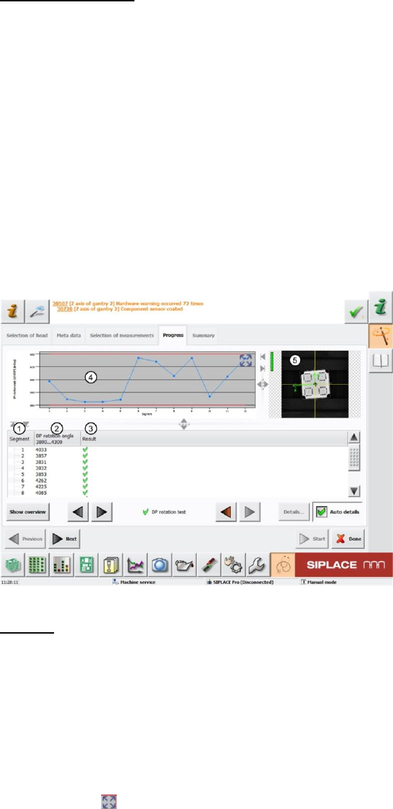
Figure 45: DP rotation results
Legend:
1. Segment measured
2. Angle of calibration component on nozzle determined DP rotation angle after evaluation by
the component camera.
The values must be within a plausible tolerance range (in our case 3.800°..4.300°).
3. Results display (OK green tick / NOK red X)
4. This diagram shows the DP rotation angle (2) values for the segments.
Blue line DP rotation angle
Red lines Upper and lower thresholds (in our case 3.800°..4.300°)
Use the button to zoom in on the diagram.
5. Evaluation image for calibration component under the component camera