0197787-01_UM_HeadVerification_708_EN.pdf - 第43页
SIPLACE Head V erification User Manual Edition 01/2015 43 4.6.4 Meaning of the Results "Vacuum open" / "Va cuum delta" / "Vacuum delta " errors at all segments: 1. Defective vacuum pump 2. S…
SIPLACE Head Verification
User Manual Edition 01/2015
42
4.6.3 Explanation of Measurement Results Using Results PDF
These results can be seen if you scroll down the "Summary" menu or generate a results PDF!
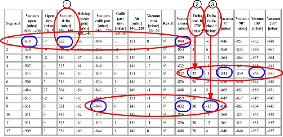
Figure 27: Results PDF for air & vacuum with head sensors
The "Vacuum delta [mbar]" (1) value is calculated by finding the difference between the "Vacuum
closed [mbar]" and "Vacuum open [mbar]" values.
In our example, we have the following calculation for segment 1:
Vacuum delta [mbar] = Vacuum open [mbar] – Vacuum closed [mbar]
Vacuum delta [mbar] = -518mbar – (-840mbar) = 322mbar
If the "Vacuum open [mbar]" is already under the tolerance threshold of -400mbar, this indicates that
the vacuum cycle for the segment is leaky. This means that, despite the nozzle opening - which
permits a certain drop in vacuum, the vacuum cycle for the segment after the nozzle must be
damaged as it is unable to form a reliable vacuum in accordance with system requirements.
If the "Vacuum open [mbar]" values is above the tolerance threshold of -800mbar, this would indicate
that the system is blocked. Either the nozzle is closed or a hose has been folded over or blocked.
The "Vacuum closed [mbar]" value describes the vacuum at a covered nozzle (simulated
component).If this value is under the upper tolerance threshold for the "Vacuum open [mbar]" value of
-800mbar, this indicates that the nozzle has not been reliably covered.
The "Delta vac. 0-270° [mbar]" (2) value is calculated from the maximum dispersion of vacuum values
at the segment angles "Vacuum 0°" - "Vacuum 270°".
In our example, segment 5 shows the greatest difference between
"Vacuum 0°" = -834mbar and "Vacuum 180°" =-866mbar.
We therefore have the following calculation for the "Delta vac. 0-270°" value:
Delta vac. 0-270° [mbar] = Min – Max = -834mbar – (-866mbar) = 32mbar
If the dispersion is too great, this indicates that the rotary axis of the segment is damaged and
therefore running eccentrically, so that the nozzle is therefore unable to make level contact with the
component.
In this case we need to look for a significant deviation in one of the values.
The "Delta calib-closed [mbar]" (3) value is calculated by finding the difference between the "Vacuum
closed [mbar]" and the "Vacuum calib part [mbar]" values.
In our example, we have the following calculation for segment 9:
Delta calib-closed [mbar] = Vacuum calib part [mbar] – Vacuum closed [mbar]
Delta calib-closed [mbar] = -845mbar – (-832mbar) = -13mbar
You can establish the degree to which there are differences between the reference run vacuum and
the vacuum on component pickup.

SIPLACE Head Verification
User Manual Edition 01/2015
43
4.6.4 Meaning of the Results
"Vacuum open" / "Vacuum delta" / "Vacuum delta" errors at all segments:
1. Defective vacuum pump
2. Seal (four-hole rubber disk) for holding circuit incorrectly fitted or damaged
Check the seal position or replace it
3. Holding circuit dirty Clean in ultrasound bath
"Vacuum open" / "Vacuum delta" / "Vacuum delta" errors at individual segments:
1. Check filter disks for air-tightness of nozzle seat Replace filter disks
2. Check nozzle Replace nozzle
3. Dirty or damaged vacuum hose to segment Replace vacuum hose
4. Holding circuit dirty Clean in ultrasound bath
"Delta vac. 0-270°" error at individual segments:
1. DP/segment defective Rotation or no planarity of nozzle contact surface Replace
DP/segment
2. Internal DP/segment vacuum cycle defective Replace DP/segment
4.7 "Head Endurance Run 01005" Measurement
The following tools are required for these measurements:
CPP: 12x nozzle type 2057 03070280-01 (calibration nozzle)
CP20A: 20x nozzle type 1235 03015222-01 (calibration nozzle)
4.7.1 Explanation of Measurement – Procedure
This measurement determines the Z actual position deviation at pickup and placement. This Z actual
position deviation is an indication of how reliably the Z axis system is working and whether it is
damaged.
This measurement is important primarily for contactless placement, for example, with 0201 or 01005
components.
The positioning speed of the DP or segments and their reliability is also checked.
The results of these measurements provide feedback about the following sources of errors:
1. Segment guides with difficulty moving or worn out
2. Linear guide of Z axis with difficulty moving
3. Defective Z motor
4. P drive or turning station of segment defective
Measurement steps:
1. The head is positioned over the height reference run position on the fixed conveyor side.
2. Segment 1 now moved towards the conveyor side very slowly with travel profile TP34 [TP34
01005 CRAWL] . As soon as the nozzle tip touches the conveyor side, the current monitoring
of the Z axis rises and the Z axis is understood to have reached the reference position for
calculating the contactless Z pickup position.From this position, a distance needed for
contactless component pickup is calculated. This position is now the target position for the
following pickup or placement cycles.
3. The Z axis now moves back up again with travel profile TP1.
4. The Z axis then determines the Z pickup position contactless for all other segments, as
described in point (2)
5. The actual determination of measurement values starts now.
6. Pickup:
Segment 1 is now moved downwards with travel profile TP34 [TP34 01005 CRAWL] and a DP
pickup angle of 0° and contactless positioned at the determined Z pickup position. The actual
Z position determined when the end position signal is emitted is known as Z-Pick [µm].
SIPLACE Head Verification
User Manual Edition 01/2015
44
The positioning time for rotation of the DP at 180° (place) after 0° (pickup) is also determined.
7. Segment 1 is then moved back up again with travel profile TP1.
8. Placement:
Segment 1 is now moved downwards with travel profile TP34 [TP34 01005 CRAWL] and a DP
placement angle of 180° and is contactlessly positioned at the determined Z pickup position.
The actual Z position determined when the end position signal is emitted is known as Z-Place
[µm].
The positioning time for rotation of the DP at 0° (pickup) after 180° (place) is also determined.
9. Segment 1 is then moved back up again with travel profile TP1.
10. This procedure is now executed 30x for segment 1, which means a total of 60x Z axis
movements (30x pickup / 30x place) and also 60x DP positioning times.
11. All pickup positions Z-Pick [µm] are saved internally and the minimum (Z min pick [µm]) and
maximum (Z max pick [µm]) positions are used for the analysis.
12. All placement positions Z-Place [µm] are saved internally and the minimum (Z min place
[µm]) and maximum (Z max place [µm]) positions are used for the analysis.
13. The positioning times for rotation of each segment by 180° are also analyzed, to provide a
minimum (Min DP Time [ms]) and maximum (Max DP Time [ms]) value for each segment.
14. The star now turns segment 2 into the placement position
15. Measurements 6-14 are now performed for all other segments.
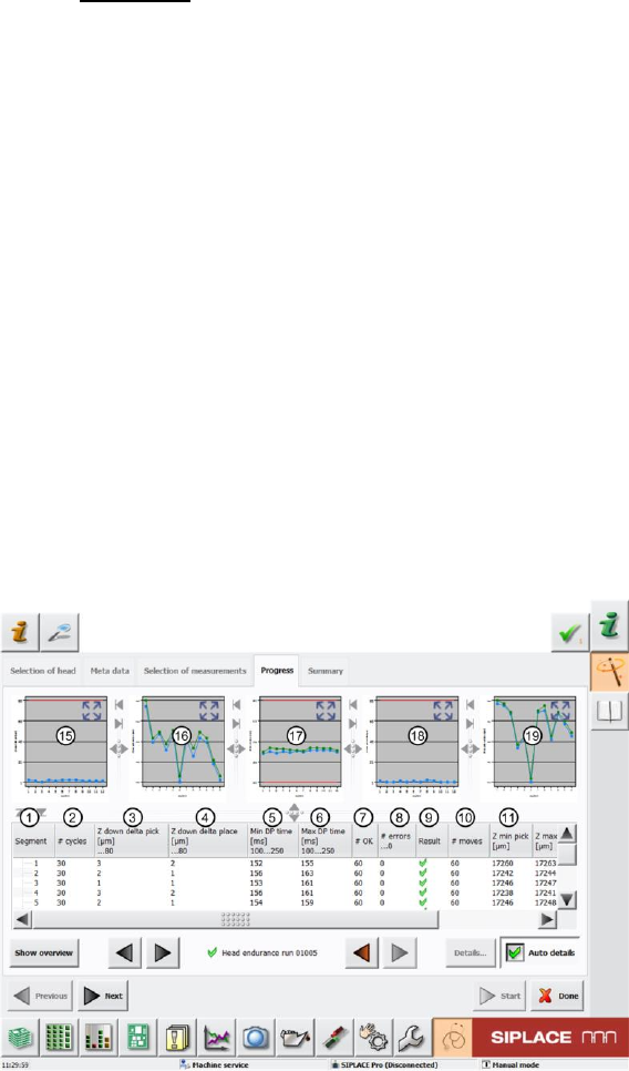
4.7.2 Explanation of Measurement Results in "Progress" Menu
After completion of the measurement, the following results appear in the "Progress" menu:
Figure 28: Head endurance run 01005_1 result