00194482-02_AI_NozzleChanger_X_605_DE+EN.pdf - 第45页
Assembly instructions Nozzle changer SIPLACE X-Series / D3 11/2011 Edition 45 : Unscrew the conta ct plates at the outer screws. 2 2 : Place as many sp acers beneath the cont act surfa c e as you need to achieve the corr…
Assembly instructions Nozzle changer SIPLACE X-Series / D3
11/2011 Edition
44
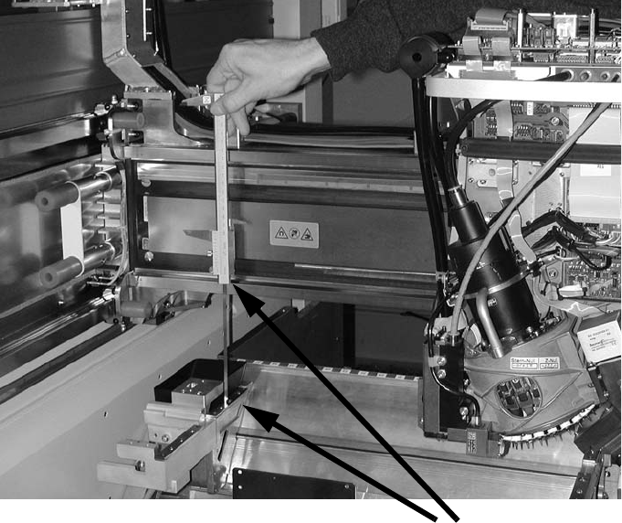
: Push the placement head outwards for the inner measurement.
: Measure the distance on the inside.
2
2
: The ideal measured value is 150.0 +/- 0.2 mm.
If the distance is correct, then start installation of the nozzle changer in the placement machine.
If the distance is greater, insert spacers beneath the contact surfaces.
2
2
2
2
2
2
2
2
2
Distance to be measured
Assembly instructions Nozzle changer SIPLACE X-Series / D3
11/2011 Edition
45
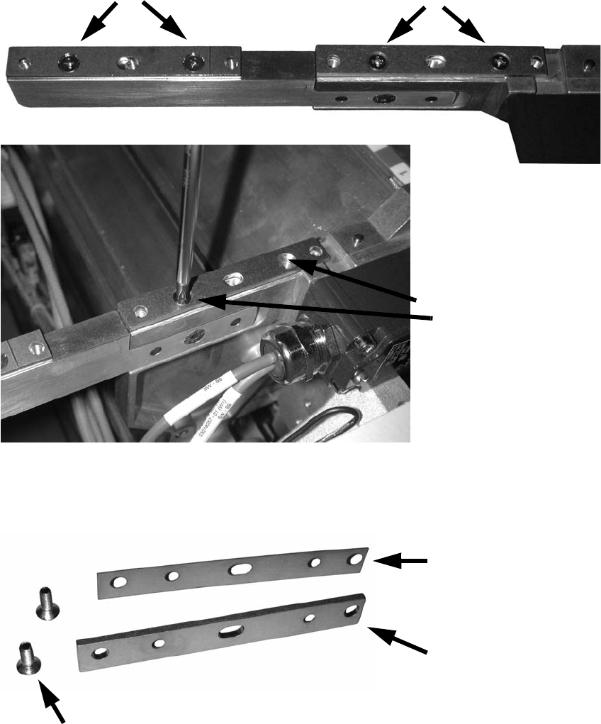
: Unscrew the contact plates at the outer screws.
2
2
: Place as many spacers beneath the contact surface as you need to achieve the correct height.
2
2
Loosen screws
2 screws
2 screws
Nozzle changer 2nd row
Nozzle changer
adjusting plate
(item no.: 03021079-xx)
Nozzle changer
contact surface
(item no.: 03021044-xx)
Screws DIN 965-M4 x 10-4.8 (item no.: 00095312-xx)
Assembly instructions Nozzle changer SIPLACE X-Series / D3
11/2011 Edition
46
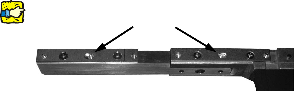
: Screw the contact surfaces on again with the spacers beneath them.
2
The slots between the fixing holes/screws are seated off-centre on the holes. 2
2
2
: Check that the distance is now correct (150.0 +/- 0.2 mm).
If it is not, then adjust the distance using the spacers.
2
2
2
2
2
2
2
2
2
2
2
2
2
2
2
2
2
2
Slots
Nozzle changer second row