00194482-02_AI_NozzleChanger_X_605_DE+EN.pdf - 第57页
Assembly instructions Nozzle changer SIPLACE X-Series / D3 11/2011 Edition 57 : Connect the second nozzle changer to the one-wir e hub. 2 2 : Place the nozzle changer onto the newly fi tted carrier with the top facing do…
Assembly instructions Nozzle changer SIPLACE X-Series / D3
11/2011 Edition
56
Fitting the second row of nozzle changers 2
2
The second row of a 12-nozzle changer can be installed wrongly.
It must not be fitted in the PCB transport direction. 2
2
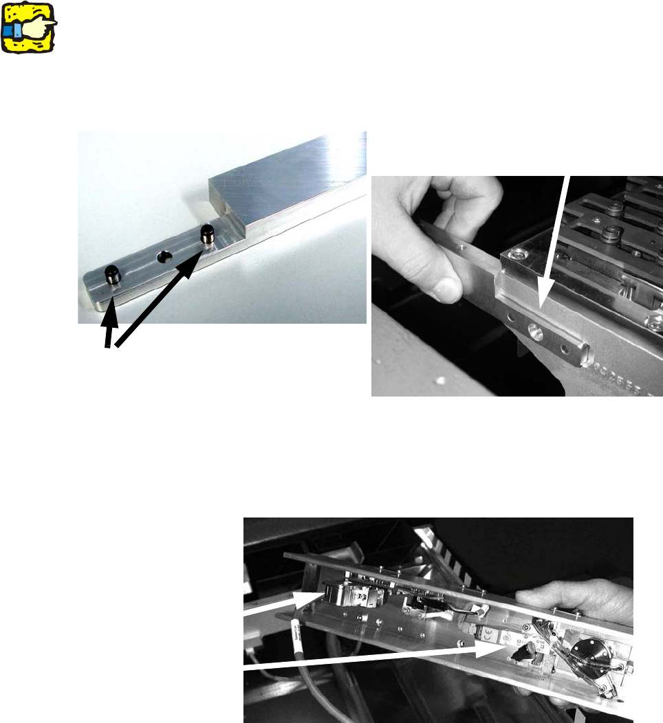
: Tap the dowel pins into the relevant holes in the bracket and screw the bracket on as shown.
2
2
: Plug the cables and the compressed air hose into the C&P head nozzle changer.
The cable for row 2 is marked "b".
2
2
2
2
2
Dowel pins
(DIN 6325 - 5m6 x 14-St, item no.: 00323142-xx)
Screw
(DIN 7991-M5 x 12-8.8, item no.: 00306624-xx)
Cable
Compressed
air connector
Assembly instructions Nozzle changer SIPLACE X-Series / D3
11/2011 Edition
57
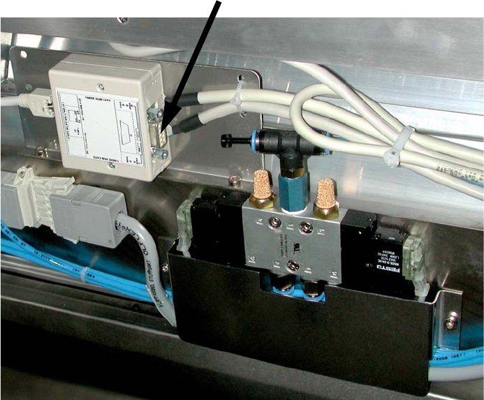
: Connect the second nozzle changer to the one-wire hub.
2
2
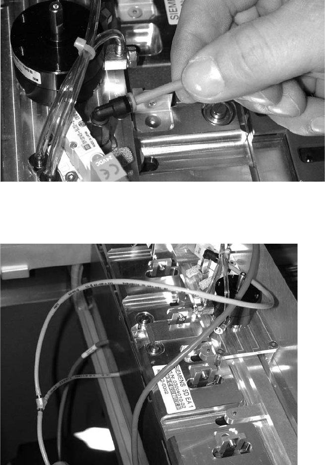
: Place the nozzle changer onto the newly fitted carrier with the top facing downwards.
: Connect the compressed air hose to the new nozzle changer.
2
2
2
2
2
2
2
2
2
2
Slot for the reject bin sensor
Assembly instructions Nozzle changer SIPLACE X-Series / D3
11/2011 Edition
58
: Put a Y connector onto the disconnected hose.
Use the Y connector to connect the compressed air hoses (2.5 bar) of both nozzle changers.
2
2
The wiring should look like this: 2
2
2
2
2
2
2