YSM40 Mainte_E.pdf - 第122页
3-54 3 Periodic maintenance items 5.6 PU axis 5.6.1 Cleaning and lubricating the PU axis ball screw 1 Make the prepar ation for cleaning. e 1. Remove all items that are affected by magnetism, such as a watch and ID card.…
3-53
3
Periodic maintenance items
5.5.2 Cleaning and lubricating the W-axis guide
1
Make the preparation for cleaning.
e
1. Remove all items that are affected by
magnetism, such as a watch and ID
card.
2. Press the emergency stop button.
3. Lower the feeder exchange carriage by
using the clamp switch and remove the
feeder exchange carriage.
2
Set the Lane 1 conveyor to its
maximum width.
1. Press the [Device] button to perform axis
movement and set the Lane 1 conveyor
to its maximum width.
2. Lower the push-up plate.
3
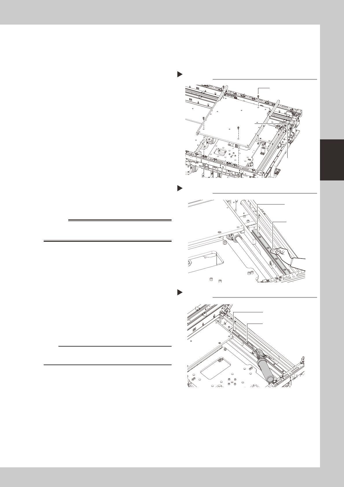
Remove the push-up plate.
e
1. Press the [Emergency Stop] button.
2. Use a hexagon wrench (4) to remove the
4 bolts which secure the push-up plate,
then remove the push-up plate.
53350-N5-00
w
WARNING
4
Clean the guide.
Using a cloth, etc., which produces no lint,
clean the entire guide, wiping off all soiling
and old grease.
53353-N5-00
5
Apply grease.
Use a grease gun (30° bend type) to inject
the prescribed grease (NSL) at the W-axis
guide's grease nipples.
53354-N5-00
6
Remount the push-up plate.
n
NOTE
Perform the Lane 2 cleaning and lubrication in the
same manner as the Lane 1 procedures.
Removing the push-up plate
Step 3
Push-up plate securing
bolts (4 bolts)
Push-up plate
Cleaning the guide
Step 4
Cleaning cloth
Guide
Applying grease
Step 5
Grease nipple
Grease gun (30° bend type)
3-54
3
Periodic maintenance items
5.6 PU axis
5.6.1 Cleaning and lubricating the PU axis ball screw
1
Make the preparation for cleaning.
e
1. Remove all items that are affected by
magnetism, such as a watch and ID
card.
2. Press the emergency stop button.
3. Lower the feeder exchange carriage by
using the clamp switch and remove the
feeder exchange carriage.
2
Set the Lane 1 conveyor to its
maximum width.
1. Press the [Device] button to perform axis
movement and set the Lane 1 conveyor
to its maximum width.
2. Lower the push-up plate.
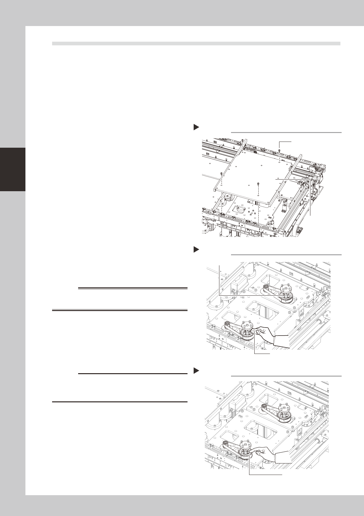
3
Remove the push-up plates (at
Lanes 1 & 2).
e
1. Press the [Emergency Stop] button.
2. Use a hexagon wrench (4) to remove the
4 bolts which secure the push-up plate,
then remove the push-up plate.
3. Release the Emergency Stop status, then
press the [Device] button to perform axis
movement which raises the PU axis to its
maximum height.
53350-N5-00
w
WARNING
4
Clean the ball screw.
e
1. Press the [Emergency Stop] button.
2. Using a cloth, etc., which produces no
lint, clean the entire ball screw, wiping
off all soiling and old grease.
53355-N5-00
c
Carefully wipe the lead grooves of the ball screw during
is not produced.
5
Apply grease.
Apply the specified grease (NSL) by hand
uniformly over the surface and lead grooves
of the ball screw.
53356-N5-00
6
Remount the push-up plate.
e
Cancel emergency stop and lower the push-
up unit. Then press the emergency stop
again and reinstall the push-up plate.
Removing the push-up plate
Step 3
Push-up plate securing
bolts (4 bolts)
Push-up plate
Cleaning the ball screw
Step 4
Cleaning cloth
Ball screw
Applying grease
Step 5
Grease
3-55
3
Periodic maintenance items
5.7 Controller
5.7.1 Cleaning the filter
There are 2 filter types that require cleaning, and they are located at the following 3 positions:
System controller filter : 1 filter at rear center of machine.
Servo controller filters
: 2 filters, 1 at the front right side, and 1 at the right side as viewed when facing the machine's rear.
1
Detach the batch change carriage.
Detach the batch change carriage, and
turn the machine power OFF to ensure
safety.
2
Remove the front cover and duct.
Remove the front cover and duct as
described in Chapter 1, section "2.1
Removing the tape cutter duct".
n
NOTE
The figure at right shows the rear side. There is no need
to remove the front-side cover and duct.
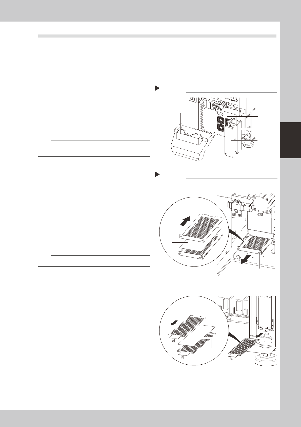
3
Remove the covers.
As shown in the figure at right, remove the
rear center cover and the right-side cover.
53370-N5-00
4
Remove the filter.
Use a Phillips screwdriver to loosen the
screws which secure the filter, then extract
the filter.
53371-N5-00
5
Clean the filter.
Use a vacuum cleaner or vacuum tool to
remove the dust sticking to the filter.
n
NOTE
If a filter replacement is not required, proceed to Step 7.
6
Replace the filter.
If the filter is too soiled to be cleaned by
air-blowing, or if it is in a degraded
condition, replace it with new one as shown
in the figure at right.
7
Reinstall the filter.
Reinstall the filter by reversing its removal
procedure.
8
Reattach the covers.
Removing the cover (machine rear)
Step 2, 3
Remove these 3 coversDuct
Front cover
Removing the filter
System controller
Servo controller
Step 4
Slide the top side
toward the front
Filter
Slide the top side
toward the rear
Filter securing screw
Filter securing screw
Filter