YSM40 Mainte_E.pdf - 第127页
4-2 4 Long-term inspection and other maintenance 2. Ever y 3 years (recommended) 2.1 Replacing the blow station filter T hereplacementprocedurefortheblowstationfilterisgivenbelo w . c …
4-1
4
Long-term inspection and other maintenance
1. Every 2 years (recommended)
1.1 Replacing the ionizer discharge needle (electrode)
Overlongperiodsofuse,thedischargeneedlecanbecomewornanditslengthshortened,resultinginan
insufficientneutralizingcapacityandreducedbalancecontrolperformance.Insuchcases,thedischarge
needleunitmustbereplacedwithanewone.Thereplacementprocedureisgivenbelow.
n
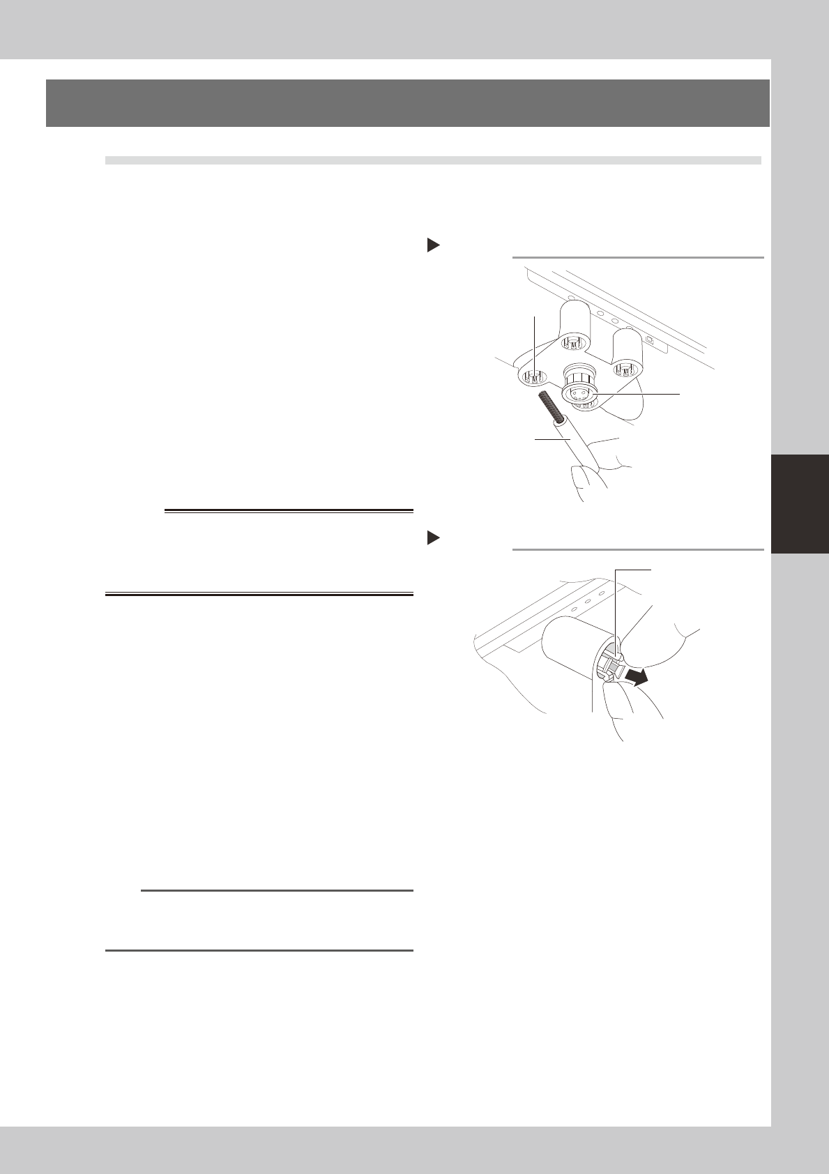
Cleaning the discharge needle
•Asoileddischargeneedle(electrode)canreducethe
ionoutputandthebalancecontrolperformance.
Therefore,thedischargeneedleshouldbecleaned
periodicallywiththeaccessorybrush.
•Thesensorshouldbecleanedoncepermonthusing
asoftclothoracottonswab.Ifthisfailsto
adequatelycleanthesensor,cleanitwithacotton
swabdampenedwithasmallamountofIPA.
53401-N5-00
n
Discharge needle replacement procedure
1
Turn the machine power OFF.
Turn the machine's main power OFF.
w
WARNING
2
Remove the discharge needle unit.
As shown at right, grasp and squeeze the
holder's opposing claws at two points and
squeeze them toward each other, then
extract discharge needle.
53402-N5-00
3
Replace the discharge needle.
When installing the new discharge needle,
the notched area on the mounting side must
be aligned with the discharge needle unit's
protruding part. When correctly aligned,
press it in.
4
Check the ion balance and the
neutralizing time.
n
NOTE
For details regarding how to check the ion balance
and the neutralizing time, refer to the manufacturer's
operation manual.
Cleaning the discharge needle
Accessory brush
Sensor
Discharge needle
Removing the discharge needle unit
Step 2
Holder claws
4-2
4
Long-term inspection and other maintenance
2. Every 3 years (recommended)
2.1 Replacing the blow station filter
Thereplacementprocedurefortheblowstationfilterisgivenbelow.
c
representative. User attempts to disassemble and clean the blow station will violate the terms of the warranty.
1
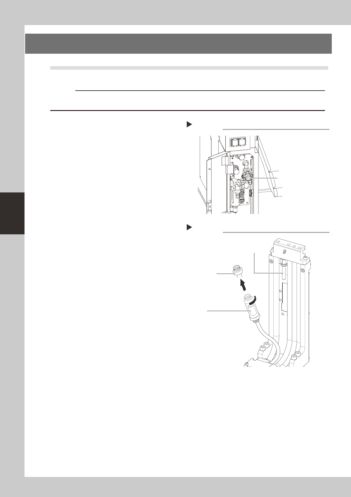
Turn the machine air supply and
power OFF.
1. End all software operations, and turn the
power switch OFF.
2. Turn the "air supply / exhaust" valve
(located inside the panel at the bottom
left of the machine's rear side) rightward
to stop the air supply.
53403-N5-00
2
Cut the tie-bands which secure the
filter.
Use nippers to cut the tie-bands which
secure the filter unit to the blow station's
stand.
3
Disconnect the air hose at one side,
then remove the filter.
1. Disconnect the air hose at one side of
the filter unit.
2. Turn the filter joint caps (at both sides of
the filter) 90° and detach them.
3. Extract the transparent case, then
extract the filter from the case.
53404-N5-00
4
Replace the filter.
Replace the removed filter with a new one,
and install it in the blow station by reversing
the Steps 2 and 3 procedure described
above.
Stopping the air supply
Step 1
Air supply / exhaust switch
Removing the filter
Step 2,3
Filter
(inside transparent case)
Filter joint cap
Disconnect this air hose
from the filter unit
4-3
4
Long-term inspection and other maintenance
2.2 UPS battery
Thebatteryisaconsumableitem.Althoughitslifevariessomewhataccordingtotheusageenvironment,the
standardbatterylifeisapproximately3years,afterwhichitmustbereplaced.TheUPSinternalbattery
replacementprocedureisgivenbelow.
w
WARNING
1
Turn the machine power OFF.
w
WARNING
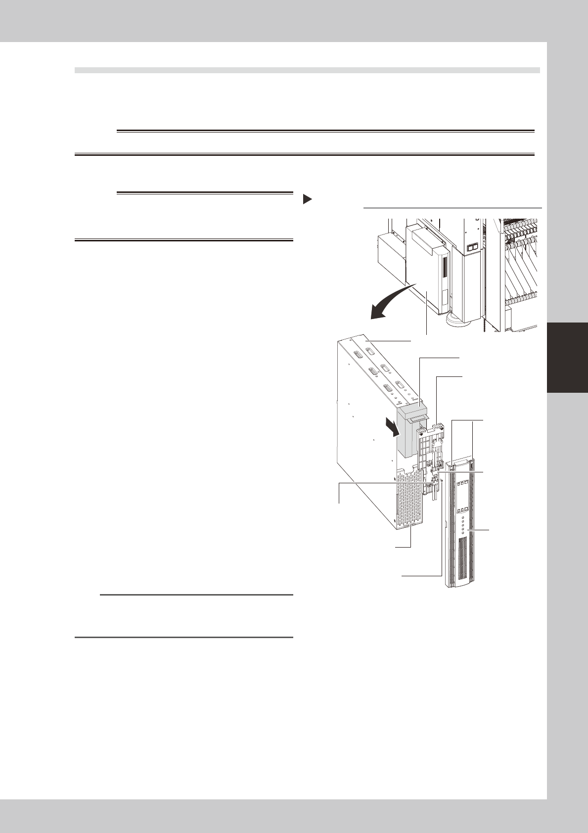
2
Remove the front panel.
Use a Phillips screwdriver to remove the
screws which secure the front panel, then
remove the front panel.
53405-N5-00
3
Disconnect the battery connector.
Disconnect the UPS side and internal battery
side connectors.
4
Remove the battery securing
fixture.
Remove the battery fixture mounting screws,
then remove the battery securing fixture.
5
Replace the removed battery with a
new one.
Extract the old battery and insert a new
battery in its place.
6
Reinstall the battery.
Reverse Steps 2 to 4 above to reinstall the
battery.
7
Check the battery condition.
1. Turn the machine power ON.
2. Press the UPS ON button and verify that
the BATTERY LED is OFF.
n
NOTE
For UPS details, refer either to the optional manual "UPS
(Uninterruptible power supply unit)" or to the
manufacturer's operation manual.
Replacing the internal battery
UPS unit
Bottom left,
as viewed when
facing the machine's
rear side
Internal battery
Internal battery
side connector
UPS side battery
connector
Battery securing fixture
Front panel
Front panel hook
Battery securing fixture
mounting screw
Front panel
mounting screws