YSM40 Mainte_E.pdf - 第137页
4-12 4 Long-term inspection and other maintenance 4.2.2 Removing the pressing plate and cup packing 1 Put a mark. Using an oil-based marker pen, put a mark on the pressing plate at the position of th e mark on the casing…
4-11
4
Long-term inspection and other maintenance
5
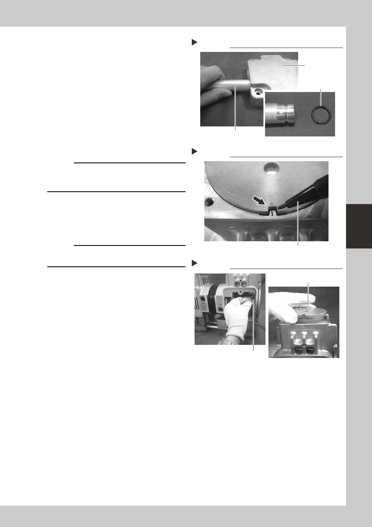
Replace the O-rings.
1. Remove the connecting pipe from the
head covers.
2. Replace the O-rings (4 pieces) on the
connecting pipe with new ones. At this
point, apply grease to the entire surface
of each new O-ring.
53424-N5-00
6
Put a mark.
Before removing the cylinder, put a mark on
the casing and cylinder with an oil-based
marker pen to indicate the reassembly
position.
53425-N5-00
c
The pump will break down if the cylinder is reassembled
the reassembly position.
7
Raise the cylinder.
Wear gloves and slowly turn the fan upward
to raise the cylinder.
8
Remove the cylinder.
c
of the cylinder installation surface.
53426-N5-00
Replacing the O-ring
Step 5
Connecting pipe
Head cover
O-ring
Marking
Step 6
Oil-based marker pen
Removing the cylinder
Step 7, 8
Cylinder
Fan
4-12
4
Long-term inspection and other maintenance
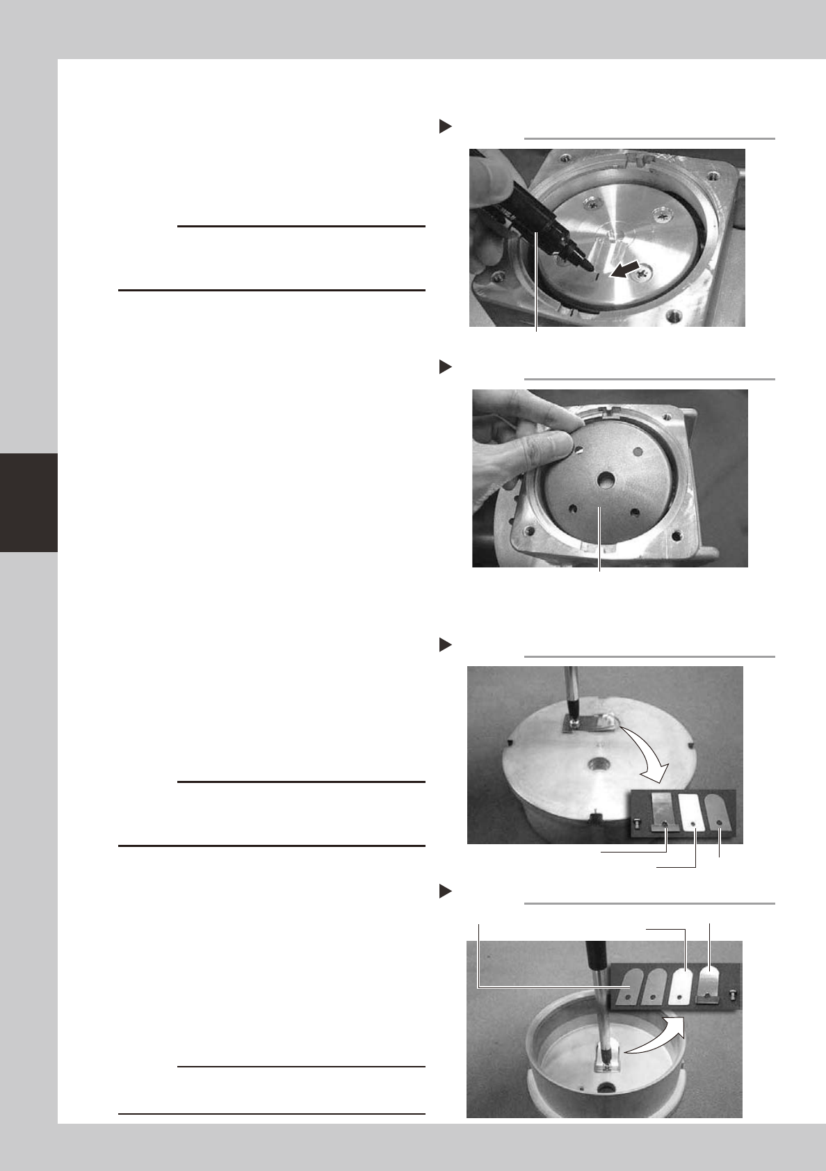
4.2.2 Removing the pressing plate and cup packing
1
Put a mark.
Using an oil-based marker pen, put a mark
on the pressing plate at the position of the
mark on the casing.
53427-N5-00
c
The pump will break down if the pressing plate is
mark to indicate the reassembly position.
2
Remove the pressing plate.
Always wear gloves and use a Phillips
screwdriver to loosen the four mounting
screws (M5×L12). Then remove and clean
the pressing plate.
3
Remove the cup packing.
53428-N5-00
4.2.3 Removing the cylinder parts
1
Remove the parts on the exhaust
valve side.
Use a Phillips screwdriver to loosen the
mounting screw and remove the exhaust
valve pressing plate, exhaust valve, and
exhaust valve backup.
53429-N5-00
c
intake valve pressing plate as they will be reused after
cleaning.
2
Remove the parts on the intake
valve side.
Invert the cylinder, loosen the mounting
screw with a Phillips screwdriver, and remove
the intake valve pressing plate, intake valves
(2 pieces), and intake valve backup.
53430-N5-00
3
Clean the cylinder.
Using a lint-free cloth moistened with a
cleaning solvent, wipe the entire cylinder.
c
put on the cylinder.
Marking
Step 1
Oil-based marker pen
Removing the cup packing
Step 3
Cup packing
Removing the exhaust valve
Step 1
Exhaust valve
Exhaust valve pressing plate
Exhaust valve backup
Removing the intake valve
Step 2
Intake valves (2 pieces)
Intake valve pressing plate
Intake valve backup
4-13
4
Long-term inspection and other maintenance
4.3 Reinstalling the replacement parts
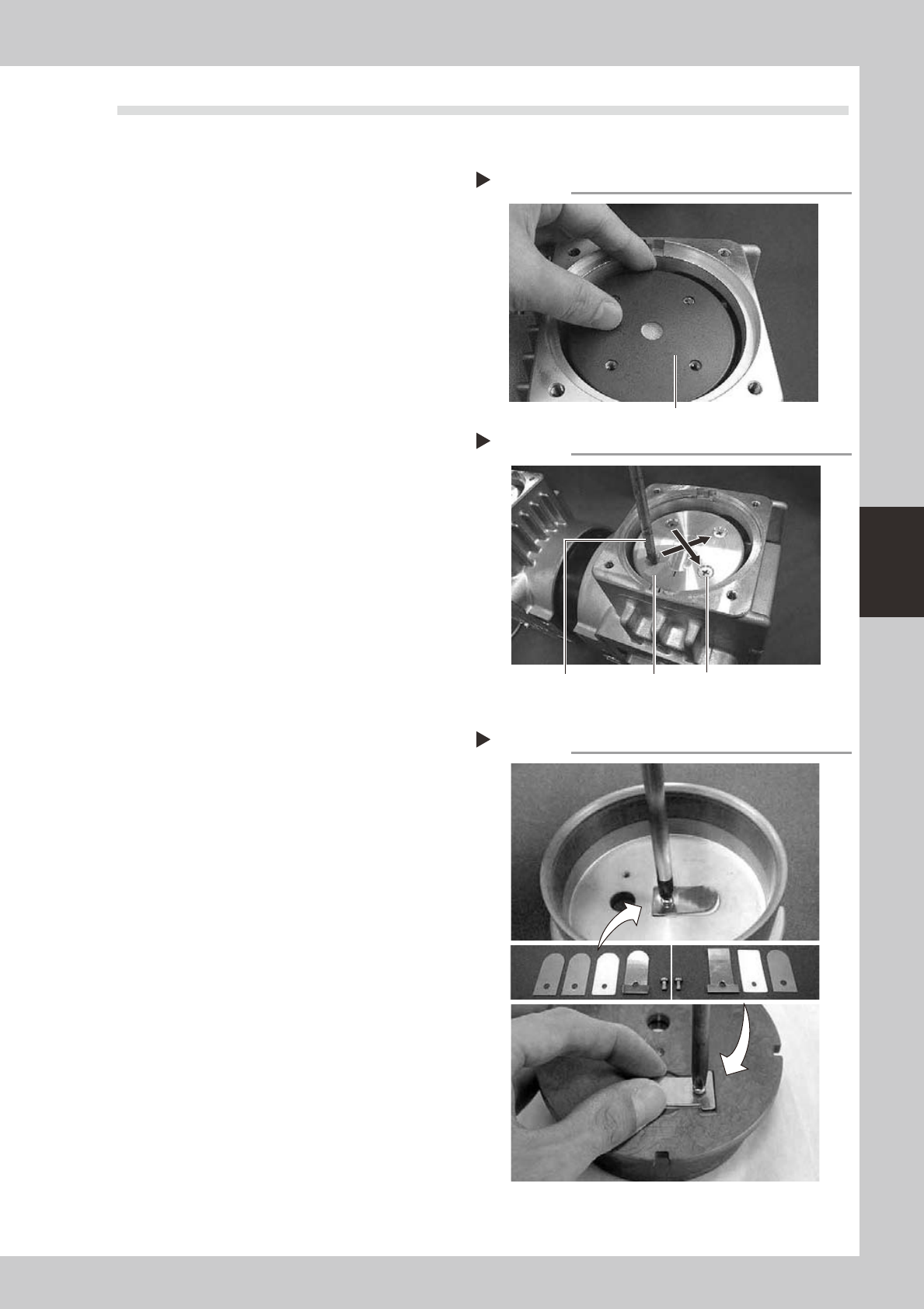
4.3.1 Reinstalling the cup packing and pressing plate
1
Place a new cup packing.
Place a new packing on the connecting
rod, with the sealing side facing down.
53431-N5-00
2
Place the pressing plate.
Place the cleaned pressing plate on the cup
packing while aligning the mark with the
mark on the casing.
53432-N5-00
3
Tighten the mounting screws.
1. Make sure the mark on the pressing plate
is aligned with the mark on the casing.
2. Use a torque limiting screwdriver to
tighten the four screws (M5×L12)
uniformly in a diagonal order.
Tightening torque: 0.55N·m
4.3.2 Reinstalling the cylinder parts
1
Reassemble the intake valve parts.
1. Place the two intake valves (FLAP) in the
cleaned cylinder and then place the
intake valve backup (SHEET1 FLAP) and
pressing plate on the intake valves.
2. Use a torque limiting screwdriver to
tighten the screw (M3×L5) to a torque of
0.55N•m while being careful not to make
contact with the concave groove in the
periphery of the cylinder.
53433-N5-00
2
Reassemble the exhaust valve parts.
1. Invert the cylinder, place the exhaust
valve on the cylinder, and place the
exhaust valve backup.
2. Place the pressing plate on the exhaust
valve, and use a torque limiting
screwdriver to tighten the screw (M3×L5)
to a torque of 0.55N•m while being
careful not to make contact with the
concave groove in the periphery of the
cylinder.
3
Insert the cylinder.
Insert the cylinder in the cup packing
section while aligning the mark on the
cylinder with the mark on the casing.
Placing a cup packing
Step 1
Cup packing
Securing the pressing plate
Step 2, 3
Mounting screwPressing plateTorque limiting screwdriver
Reinstalling the cylinder parts
Step 1