YSM40 Mainte_E.pdf - 第129页
4-4 4 Long-term inspection and other maintenance 3. Inspecting, cleaning and lubricating the cA TS The table below shows a list of checkpoints for each inspection location. Inspection location Unit name Checkpoints Inspe…
4-3
4
Long-term inspection and other maintenance
2.2 UPS battery
Thebatteryisaconsumableitem.Althoughitslifevariessomewhataccordingtotheusageenvironment,the
standardbatterylifeisapproximately3years,afterwhichitmustbereplaced.TheUPSinternalbattery
replacementprocedureisgivenbelow.
w
WARNING
1
Turn the machine power OFF.
w
WARNING
2
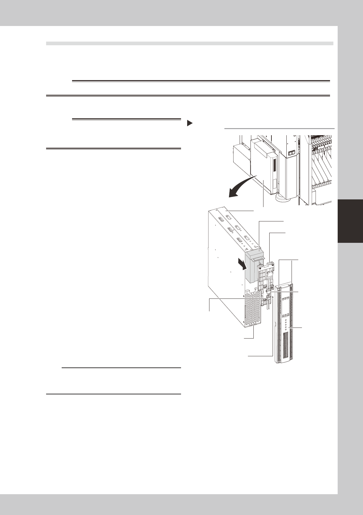
Remove the front panel.
Use a Phillips screwdriver to remove the
screws which secure the front panel, then
remove the front panel.
53405-N5-00
3
Disconnect the battery connector.
Disconnect the UPS side and internal battery
side connectors.
4
Remove the battery securing
fixture.
Remove the battery fixture mounting screws,
then remove the battery securing fixture.
5
Replace the removed battery with a
new one.
Extract the old battery and insert a new
battery in its place.
6
Reinstall the battery.
Reverse Steps 2 to 4 above to reinstall the
battery.
7
Check the battery condition.
1. Turn the machine power ON.
2. Press the UPS ON button and verify that
the BATTERY LED is OFF.
n
NOTE
For UPS details, refer either to the optional manual "UPS
(Uninterruptible power supply unit)" or to the
manufacturer's operation manual.
Replacing the internal battery
UPS unit
Bottom left,
as viewed when
facing the machine's
rear side
Internal battery
Internal battery
side connector
UPS side battery
connector
Battery securing fixture
Front panel
Front panel hook
Battery securing fixture
mounting screw
Front panel
mounting screws
4-4
4
Long-term inspection and other maintenance
3.
Inspecting, cleaning and lubricating the cATS
The table below shows a list of checkpoints for each inspection location.
Inspection location Unit name Checkpoints
Inspection
interval
Magazine and pallet Deformation, wear and deterioration Daily
AZ axis
Guide Adhesion of foreign matter, rust, and grease condition
DailyBelt Belt looseness, wear and deterioration
Ball screw Adhesion of foreign matter, rust, and grease condition
AH axis
Guide Adhesion of foreign matter, rust, and grease condition
6 months
Belt Belt looseness, wear and deterioration
Ball guide Adhesion of foreign matter, rust, and grease condition
Rack & pinion Adhesion of foreign matter, rust, and grease condition
Parts supply station Wear on guide, looseness or play of pallet clamp
Pickup station
Pallet guide Deformation, wear and deterioration of screw guide and pallet guide
Belt Belt looseness, wear and deterioration
Guide Adhesion of foreign matter, rust, and grease condition
Magazine shaft Ball guide Adhesion of foreign matter, rust, and grease condition
n
NOTE
Use only the greases (grease name: NSL) specified by YAMAHA.
4-5
4
Long-term inspection and other maintenance
3.1 Monthly inspection
3.1.1 AZ axis
ThefollowingdescribesthecleaningandlubricationproceduresfortheAZaxis.
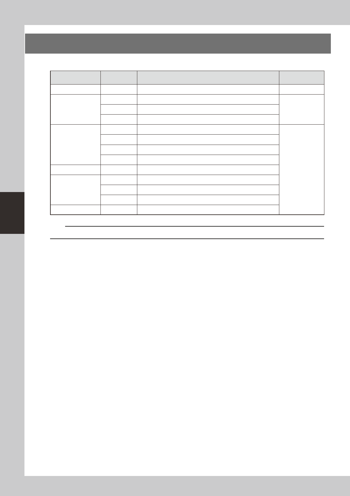
1
Remove the cover.
Use a Phillips screwdriver to remove the rear
cover of the cATS.
53410-N5-00
2
Clean the ball screw and guide.
Use a lint-free cloth to wipe off the old
grease and dirt on the ball screw and guide.
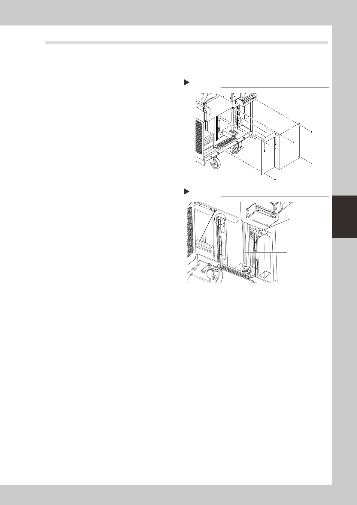
3
Apply grease.
Apply grease by hand to the ball screw. Also
apply grease to the guide using a grease
gun (bent type).
53411-N5-00
4
Reattach the cover.
Reattach the cover that was removed in
Step 1.
3.1.2 Both sides of cATS
Lightlyapplythespecifiedgrease((NSL)tothecamfolloweronbothsidesofthecATS.SeeChapter5
“Lubricationpoints”forgreasinglocations.
Applying grease
Step 3
Grease nipple
for AZ axis guide
AZ axis ball screw
Removing the cover
Step 1
Cover