TR7500_Hardware_en.pdf - 第28页
27 S t e p 5 : A f t e r ba c k up , c l o s e t he o r i g i n a l P L C p r og r a m . T h e n c l i c k o n F i l e t o O p e n t h e HC I i n t e r f a c e p r og r a m ( * . f p ) y o u w i s h t o upda t e a s s h …
26
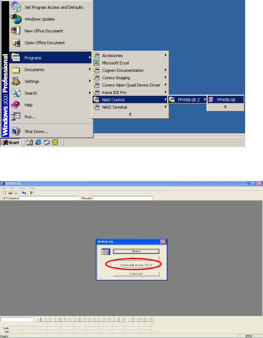
Step 3: Enter the FPWIN GR software program and as shown in the figure below, click on
Upload from PLC.
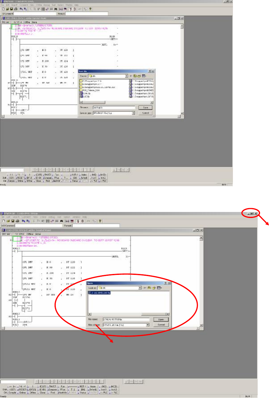
Step 4: After uploading, click on File and select Save so as to make a backup of the original
files as shown in the figure below:
27
Step 5: After backup, close the original PLC program. Then click on File to Open the HCI
interface program (*.fp) you wish to update as shown in the figure below.
CLOSE
Select the program file to use for update (*.fp)
28
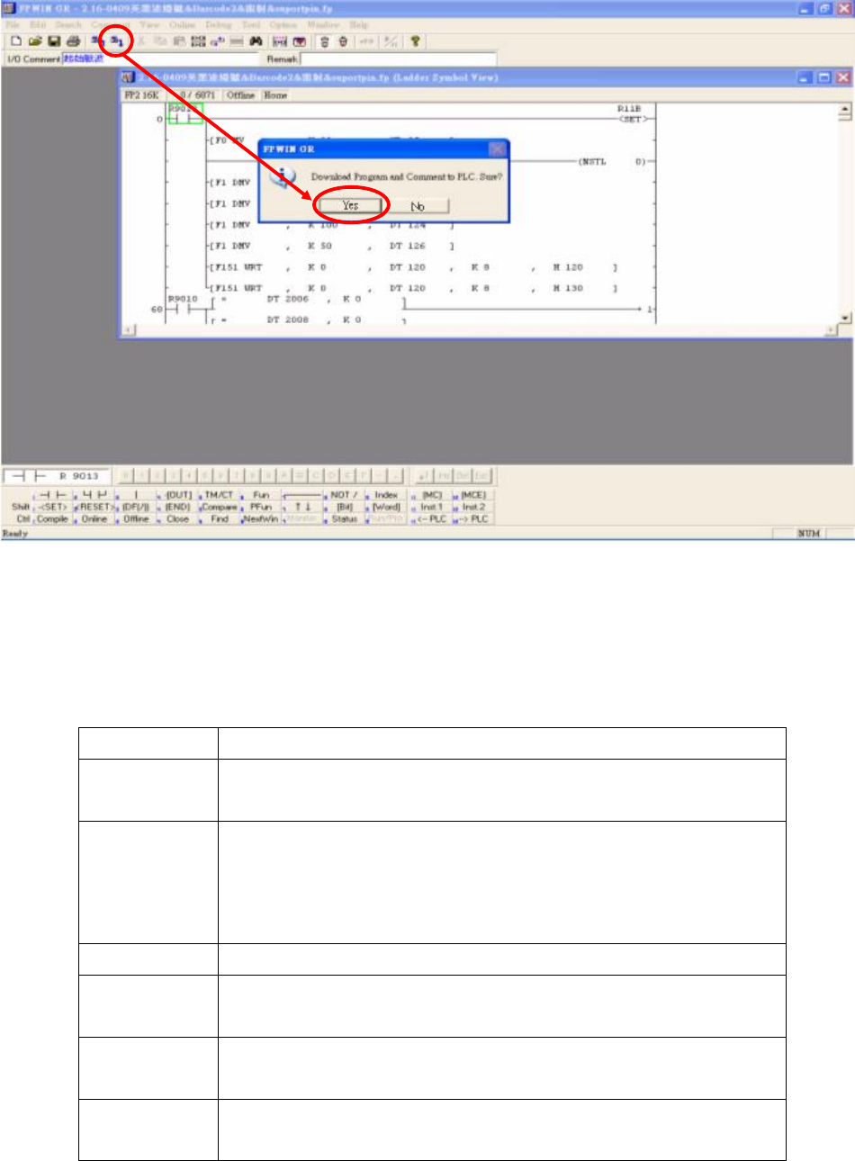
Step 6: Click on the icon in the menu (Download to PLC), click Yes to confirm overwrite of
existing program as shown in the picture below:
Step 7: Wait for the PC to transfer the data to the PLC, and the program will be updated.
1.6 PLC Hardware Overview
1.6.1 CPU(FP2-C1) Unit
1.6.1.1 Status indicator LEDs
LED Description
RUN (green) This lights in the RUN mode, to indicate that the program is
begin executed. It flashes during forced input/output.
PROG. (green)
This lights in the PROG. mode. Operation stops while this LED
is lighted. It flashes when waiting for connection of slave
station on remote I/O system. If the memory is initialized, the
brightness dims, indicating that initialization is being executed.
TEST (green)
This lights in the test operation mode.
BREAK
(green)
This lights in the operation halts at a break during a test run or
halts during the step operation mode for the test run.
ERROR (red)
This lights if an error is detected during the self-diagnostic
function.
BATT. (red)
This lights when the voltage of the backup battery drops below
a specific value.