TR7500_Hardware_en.pdf - 第35页
34 3 . 4 Wir i ng D i a g r am B r o w n R e d O r an g e Y e ll ow D o N o t C o n ne c t O t he rs C o nn e c t t o t he C li e n t end R ed B r o w n R ed G r een
33
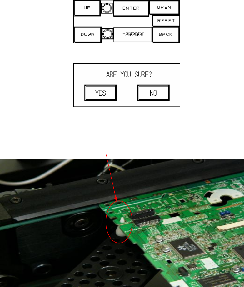
indicator lights. If the indicator light is lit, it means the limit has been reached.
Figure 2.3
Figure 2.4
Figure 2.5
The point the SUPPORT PIN needs to support.
34
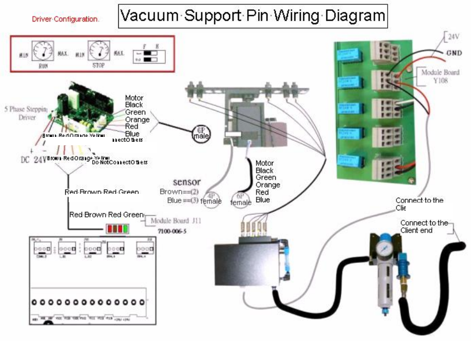
3.4 Wiring Diagram
Brown Red Orange Yellow
Do Not Connect Others
Connect to the
Client end
Red Brown Red Green
35
4 Module Board
4.1 Architecture and Function
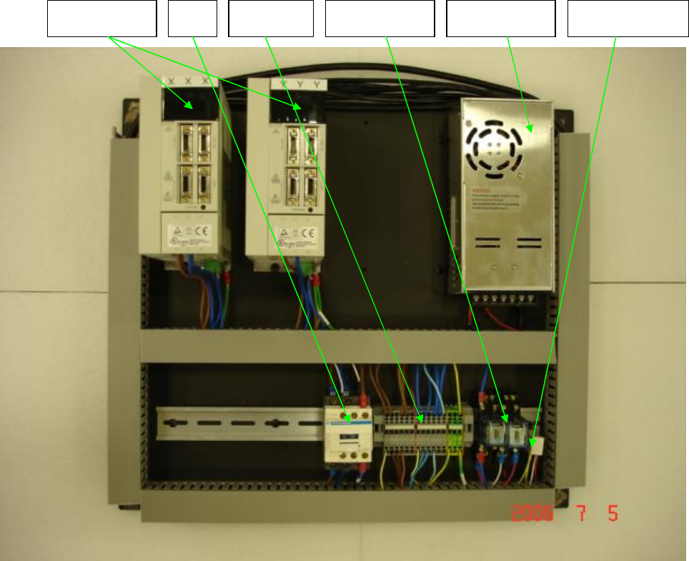
4.1.1 TR7500 Front Module Board Layout
MC
Servo Driver
Power Supply
AC Bus Relay
Current Rectifier