TR7500_Hardware_en.pdf - 第32页
31 2 C on ve y o r B e l t 2 . 1 A r c h i t ect u r e a n d F u n ct io n l T h e m a i n f un c t i on o f t h e c o n v e y o r be l t i s t o t r a n s p o r t t h e P C B a n d c o m p l e t e t h e l o a d i n g / …

30
LED Description LED on LED off LED blinks
A Pulse output signal A
display
------
During stop During
pulse
output
B Pulse output signal B
display
Reverse direction
command
Forward direction
command
-----
CL Counter clear signal
output display
Output:on Output:off
-----
D Near home status
display
On Off
-----
Z Home input status
display
On Off
-----
PA Pulser signal input
display
Display input status of pulser input signal A
PB Pulser signal input
display
Display input status of pulser input signal B
ERR Setting value error
display
Setting
value:error
Setting
value:normal
-----
1.6.3 I/O (FP2-XY64D2T & FP2-Y16P) Unit
l Please Refer to Table 2.1 I/O(PF2-XY64D2T&PF2-Y16P)
31
2 Conveyor Belt
2.1 Architecture and Function
l The main function of the conveyor belt is to transport the PCB and complete the
loading/unloading operations. Long term operation of the machine platform may lead to the
conveyor belt not being fully set on the drive axle, so users are advised to check that the
front and back conveyor belts are set properly on their axles before beginning operations to
extend the service life of the conveyor belt; if the belt needs to be replaced, first fit the belt
on to the drive axles on both ends before fitting it in order over the inner axles.
2.2 Sensor Adjustment and Replacement
1. Sensor 1 & 4 (Loading/Unloading Sensor): use the adjustment rod to adjust the Sensor
sensitivity until the indicator light is lit. (If there is an obstruction over the Sensor, the indicator
light will be lit, if there is no obstruction over the Sensor, the indicator will be off.) Then
gradually reduce it until the indicator light goes off. This will be the optimal sensor status for
Loading/Unloading.
2. Sensor 2 & 3 (Brake and Stop Sensor): adjustment method as above, but the LED light base
must be moved into position above the Sensor to check if the LED light base will interfere to
cause faulty operation. If interference does occur, the Sensor’s sensitivity needs to be
reduced until it is no longer affected by the LED light socket but still able to sense the
candidate board.
3. Sensor 5 & 6: (Holder Motor Sensor): Lowers the holder mechanism to its lowest position
along with the Sensor as well. Move the Sensor upwards until the indicator light is lit, then
move it slowly downwards again until the indicator light goes off for the correct setting.
4. Replacement: If the Sensor is not working, then the Sensor’s sensitivity should be re-adjusted.
If it still does not operate, replace with a new sensor. Replacement Method: first disconnect
the Sensor connector, and then remove the Sensor. Attach the new Sensor then connect and
secure the Sensor’s connectors. Once replacement is complete, adjust as directed in the
adjustment method.
32
3 Support Pin
3.1 Architecture and Function
Uses an external Support Pin with the HCI used to set the Support Pin’s range of lift to
compensate for PCB board flex.
3.2 Installation
The Support Pin’s motor link wire and Sensor link wire are connected directly to the sockets
in the back of the machine (Sensor 7 and Width Control Motor). This completes the hardware
installation.
3.3 Configuration Procedure
l Configuration Explanation
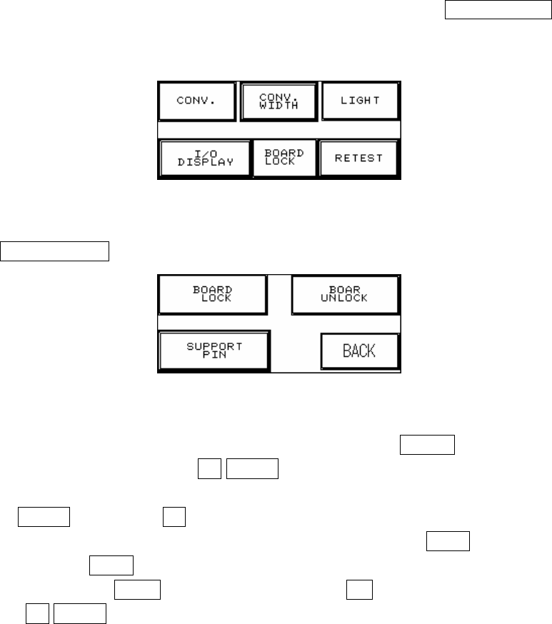
1. Press on the top and left corner of the HCI to enter Figure 2.1, press BOARD LOCK to enter
Figure 2.2.
Figure 2.1
2. Press SUPPORT PIN setting to enter Figure 2.3.
Figure 2.2
3. Place the candidate board at the loading Sensor and press ENTER. Wait until the Support
Pin is in position then press the UP/DOWN button to gradually adjust it up and down. First it
needs to be moved to the lowest position (the lower limit indicator light will be lit) and then
press RESET. Now press UP to adjust it to the location to support the candidate board as
shown in Figure 2.5 below. The setting value will be shown at -******, and when setting is
complete press BACK. If this accessory was not purchased or is not in use, please make
sure that you press OPEN and at Figure 2.4 choose NO (or it can not be reset). To the right
of the UP/DOWN buttons are their respective upper and lower elevation limit Sensor