TR7500_Hardware_en.pdf - 第65页
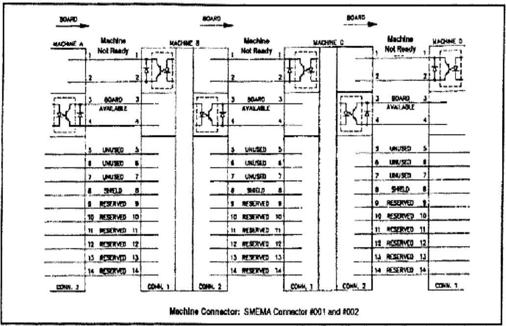
64 l T h e s t anda r d S M E M A si gn a l l i n k i s a s s h o w n i n f i gu r e be l o w .
63
6.5.3.1 LOADER
PORT1=UP LINE : Y104-Black(1) / Green (2) ->Ready
: X8A-Red(3) / Blue(4) ------->Board available
: X8B-Yellow (5)/ White(6) ->Spare
l Located below the power supply socket in the back of the equipment is I/O PORT1. Connect
the connector, and there are three sets of different colored wire pairs at the connector end.
These are: Black-Green (Y104) for requesting board from Loader, Red-Blue (X8A) reserved
INPUT connector and the Yellow-White (X8B) reserved INPUT connector. Connect the
Black-Green connector to the Loader Board Request connection. (We use the standard
SMEMA signal. If this is different due to differences in manufacturer, contact the front stage
manufacturer to acquire the connection data.)
6.5.3.2 UNLOADER
PORT2=DOWN LINE : X98-Black(1) / Green(2) --> Ready
: Y106-Red(3) / Blue(4) --> Board available
: Y105-Yellow(5) / White(6)--> (OK: Short ; NG: Open)
l Located below the power supply socket in the back of the equipment is I/O PORT2. Connect
the connector, and there are three sets of different colored wire pairs at the connector end.
These are: Black-Green (X98) for receiving READY board request signal from the Unloader,
Red-Blue (Y106) board unload signal to the Unloader and the Yellow-White (Y105) TEST
PASS signal connector. Connect the Black-Green connector with the Unloader’s connector
for sending READY board request signal. Then connect the Yellow-White connector with the
Unloader TEST PASS signal receiving signal. (We use the standard SMEMA signal. If this is
different due to differences in manufacturer, contact the front stage manufacturer to acquire
the connection data.)
l EXPLAIN
GO IN TRI-PORT1
Y 104 ( OUT ) Main station request to insert board could be used as " not busy "
X8A ( IN ) missing in documentation!!! "board available"
GO OUT TRI-PORT2
X98 ( IN ) Backward station READY could be used as " not busy"
Y106 ( OUT ) missing in documentation!!! "board available"
Y105 ( Out ) TEST OK "pass"
64
l The standard SMEMA signal link is as shown in figure below.
65
6.6 X-Y TABLE ALARM
l XY TABLE: The Driver display can indicate if there is an error. If there is, then it is a
hardware error. Please refer to the Alarm code in the reference table and trouble shoot; if no
error is displayed, operate with EzLINK. If control is possible, then there is no problem with
the hardware and this could be a X-Y Table error caused by software. Please contact FAE
personnel. The confirmation procedure is as follows:
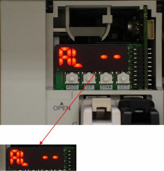
6.6.1 Check Driver Error Codes
l If LED is not showing this display, please press MODE button to switch.