TR7500_Hardware_en.pdf - 第60页
59 6 . 3 . 2 . 2 R e p l a c e m e n t l D r i v e r : F i r s t t u r n o f f t he p o w e r t h e n r e mo v e t h e t w o s e t s o f w i r e s a n d t w o D C + 24 V po w e r s upp ly c ab l e s f r o m t h e D r i v…
58
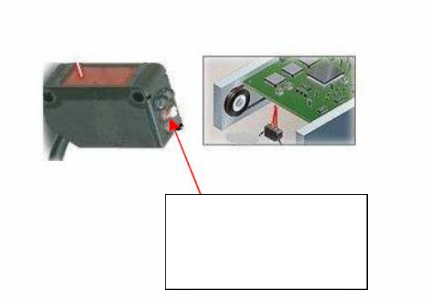
6.3.1 Sensor Problem-Adjustment:
l Sensor 1 & 2 & 4: Place the candidate board on the Sensor to be tested, and use the
adjustment rod to adjust the Sensor’s optimal detection range (When there’s a candidate
board waiting to be tested over the Sensor, the Sensor’s indicator light will glow red. If there
is no candidate board over the Sensor, the indicator light will turn off.)
l Sensor 5 & 6: Lowers the holder mechanism to its lowest position along with the Sensor as
well. Move the Sensor upwards until the indicator light is lit, then move it slowly downwards
again until the indicator light goes off for the correct setting.
l If there is no response from the Sensor, first re-adjust the Sensor sensitivity. If there is still
no response, do not attempt repair, replace with new Sensor. Replacement: If the Sensor is
not working, then the Sensor’s sensitivity should be re-adjusted. If it still does not operate,
replace with a new sensor. Replacement Method: first disconnect the Sensor connector, and
then remove the Sensor. Attach the new Sensor then connect and secure the Sensor’s
connectors. Once replacement is complete, adjust as directed in the adjustment method.
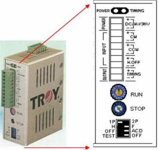
6.3.2 Check Stepping Motor Driver Problem
6.3.2.1 Are the RUN & STOP currents set to 80% and the switch positions as below? If
not, please configure them using the procedure below:
Sensor
Adjustment and
Indicator Light
59
6.3.2.2 Replacement
l Driver: First turn off the power then remove the two sets of wires and two DC +24V power
supply cables from the Driver. There’s a screw at the top and bottom of the driver, remove
the screws to install the new Driver. Once replacement is complete, reconnect the wiring
and power cables. After replacement re-adjust the driver using the adjustment method.
l Conveyor Motor: On top of the conveyor motor there is a clamped screw. Use a hex key
wrench to remove it, then insert the hex key wrench inside to unfasten the screw. Once the
screw is loosened the axle can be removed. Now unfasten the four screws around the motor
and remove the wire linking it to the machine. The motor can now be removed.
60
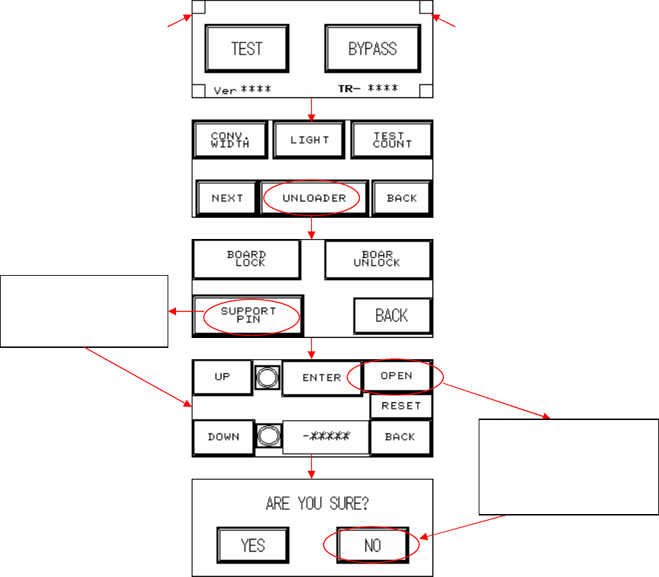
6.4 Holder Motor
l Elevation Motor Not in Position: First perform a test manually (press the two hidden buttons
simultaneously, the configuration procedure is as figure below) to check if it’s a problem with
the holder motor or with the support motor (if support device is not installed, please do not
activate this option. If accidentally pressed please select NO). Observe the results and refer
to the following table to troubleshoot.
If Suppor
t device
does not operate,
press here to test or
re
-
test
Hidden button Hidden button
If no Support device
fitted, do not press
OPEN. If accidentally
pressed, please select
NO.