00198705-01_AI_Portalmodularität_SX12_V3_DE_EN.pdf - 第103页
3 Fitting the Gantry 3.5 Connecting the Trailing Cable Assembly Instructions / Montageanleitung SIPLACE SX1/SX2 V3 Gantry Modularity Portalmodularität 05/2020 103 3.4.1 Fitting the Short End Position Buffer The short end…
3 Fitting the Gantry
3.4 Installing the Gantry
102 Assembly Instructions / Montageanleitung SIPLACE SX1/SX2 V3 Gantry Modularity Portalmodularität 05/2020
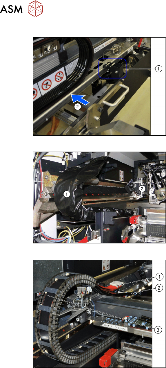
Remove the tilt guard and move in the gantry
Fig.31: Opening the tilt guard
► Open the tilt guard (1).
► Push the gantry (2) into the machine so
that both sides of the gantry rest on the
two linear guides.
► Move the gantry lift with the gantry car-
rier out of the location.
Fig.32: Pulling the trailing cable
► Move the gantry (2) into the machine
so that the trailing cable (1) can be
pulled underneath, through the gantry.
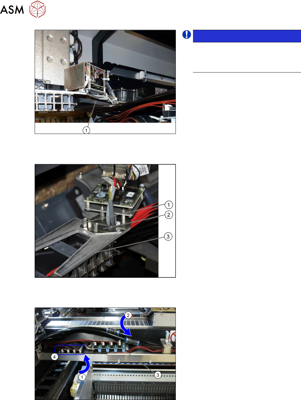
Fig.33: Flat ribbon cable and pneumatic connections
► Carefully place the flat ribbon cable (1)
and the pneumatic connections (2) over
the gantry.
► Remove the black plastic foil. A cable
tie fixes the black plastic foil to the trail-
ing cable(3).
3 Fitting the Gantry
3.5 Connecting the Trailing Cable
Assembly Instructions / Montageanleitung SIPLACE SX1/SX2 V3 Gantry Modularity Portalmodularität 05/2020 103
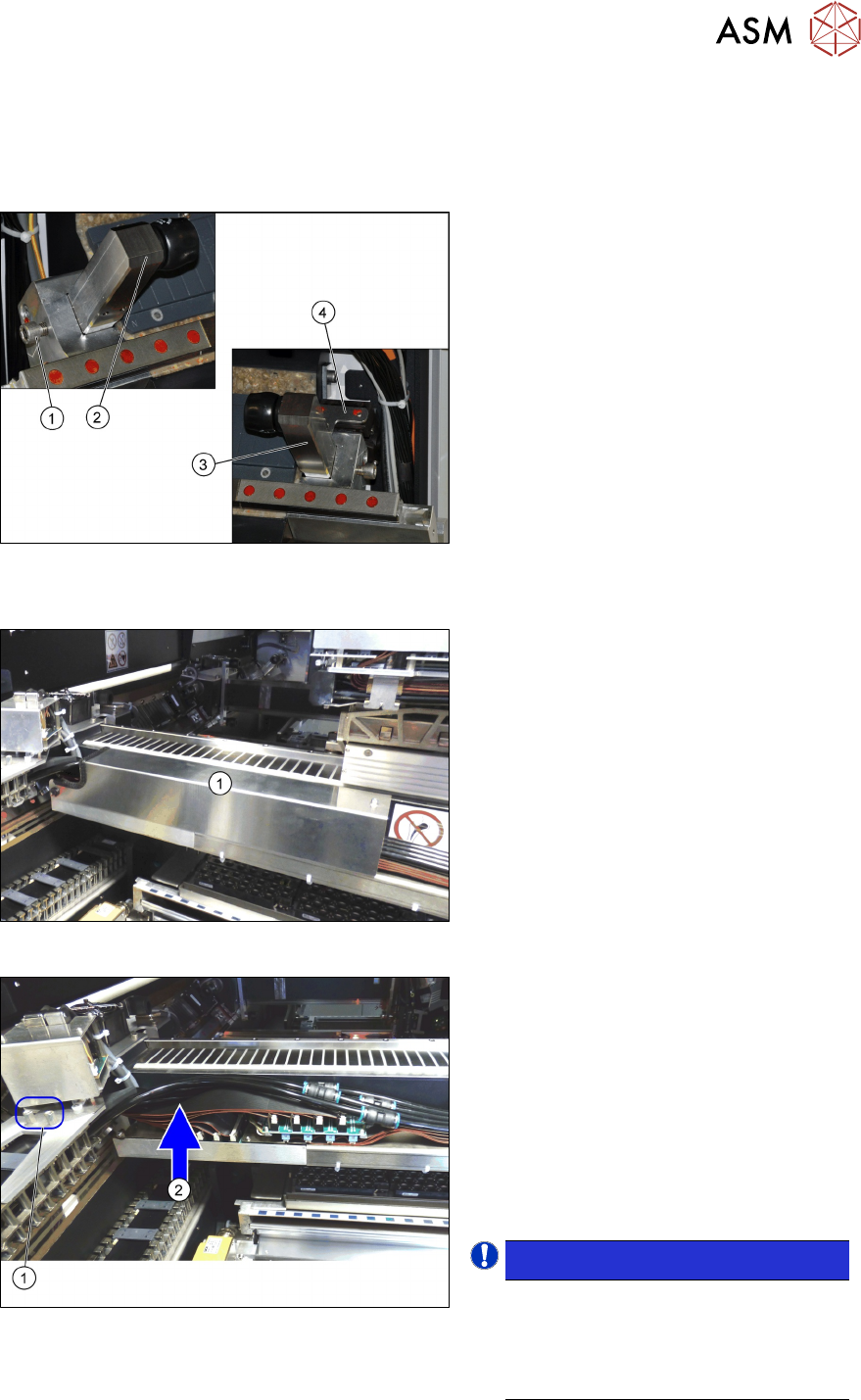
3.4.1 Fitting the Short End Position Buffer
The short end position buffer must be fitted in SIPLACE SX machines with two gantries.
This buffer needs to be removed and replaced with the long end position buffer in SIPLACE SX
machines with one gantry at location 1.
► Fit the end position buffer (2) to the left
side.
► Fit the end position buffer (3) to the
right side. The safety switch (4) for the
buffer monitoring function must engage
in the Schmersal switch.
► Tighten the fastening screws (1) for the
buffers with a torque of 14Nm.
3.5 Connecting the Trailing Cable
Fig.34: Cover
► Remove the cover (1) over the gantry
interface. To do this, remove the two
fastening screws on the right side and
carefully open the bottom left pushbut-
ton.
Fig.35: Fitting the trailing cable
► Fit the trailing cable holder (1) from
below, to the gantry distributor holder.
See the following section.
► Carefully place the flat ribbon cable and
the pneumatic hoses to one side (2).
► Make sure you do not damage the
cables and hoses.
► Take care that the alignment is correct
and that all cables and hoses are run
above one another and evenly.
NOTICE!
Use the correct gantry with Gig E trail-
ing cable, since only this can be con-
nected as described. It is not possible
to connect an older gantry with hotlink
trailing cable.
.
3 Fitting the Gantry
3.5 Connecting the Trailing Cable
104 Assembly Instructions / Montageanleitung SIPLACE SX1/SX2 V3 Gantry Modularity Portalmodularität 05/2020
Fig.36: Heat-shrinkable hose
NOTICE!
When fitting the trailing cable, make
sure that the heat-shrinkable sleeve (1)
protects the flat ribbon cable under the
Y sensor module holder.
.
Trailing cable holder - overview
Fig.37: Trailing cable mount
1. Two hexagon spacer bolts M4 x 10 mm.
2. Gantry board holder
3. Trailing cable holder
► Remove the two hexagon spacer bolts
M4 x 10 mm on the trailing cable
holder.
► Hold the trailing cable holder from
below, on the gantry board holder.
► Screw the two hexagon spacer bolts
from above, into the trailing cable
holder.
► Secure the two hexagon spacer bolts
with Loctite 241.
Restore the electrical and pneumatic connections
Fig.38: Electrical and pneumatic connections
► First connect the seven flat ribbon
cables (1) to the boards for the gantry
interface of the X axis (3) and the
gantry interface of the Y axis (4). The
sequence depends on the different
cable lengths. Work your way from
back to front.
► Remove the dummy plugs from the
pneumatic hose couplings.
► Connect the four pneumatic connec-
tions for the trailing cable to the gantry
connections (2). The sequence de-
pends on the different hose lengths.