00198705-01_AI_Portalmodularität_SX12_V3_DE_EN.pdf - 第82页
2 Brief Description 2.1 Overview 82 Assembly Instructions / Montageanleitung SIPLACE SX1/SX2 V3 Gantry Modularity Portalmodularität 05/2020 2.1.4 Configurations 2.1.4.1 Table Positions The table position required for the…
2 Brief Description
2.1 Overview
Assembly Instructions / Montageanleitung SIPLACE SX1/SX2 V3 Gantry Modularity Portalmodularität 05/2020 81
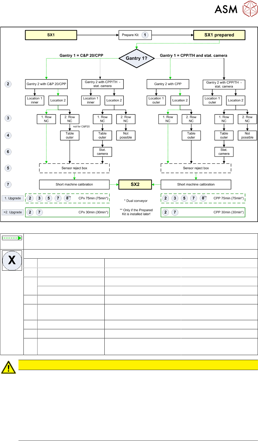
Fig.6: Upgrade of SX1 and SX1 prepared
These arrows show the gantry upgrade procedure involving the least work for the relev-
ant machine types.
Work to be performed:
1 Prepared kit 180 min SIPLACE Service
2 Rerail gantry 15 min Customer
3 NC row 1 30 min Customer
NC row 2 20 min Customer
4 Outer table position 60 min SIPLACE Service, customer
5 Reject bin sensors (op-
tional)
15 min Customer
6 Stationary cameras 30 min SIPLACE Service, customer
7 Calibrating the machine 15 min Customer
8 PCB/component map-
ping
30 min per conveyor lane CPx
70 min per conveyor lane TH
SIPLACE Service, customer
CAUTION
PCB/component mapping
If a SX1 prepared or a prepared kit is installed at the customer site and a second gantry is
mounted for the first time, a complete PCB/component mapping for the 2nd gantry is required.
This is necessary because of the extended Y-traversing path and the Y-drive motor lying on
the other side of the machine.
Component mapping is always required for a gantry upgrade with Twin Head (VHF TH).
Recommendation: if gantries are replaced, component mapping should be performed for
process reliability (accuracy) reasons.
(See 4.2 "Performing Calibration" [}119])
2 Brief Description
2.1 Overview
82 Assembly Instructions / Montageanleitung SIPLACE SX1/SX2 V3 Gantry Modularity Portalmodularität 05/2020
2.1.4 Configurations
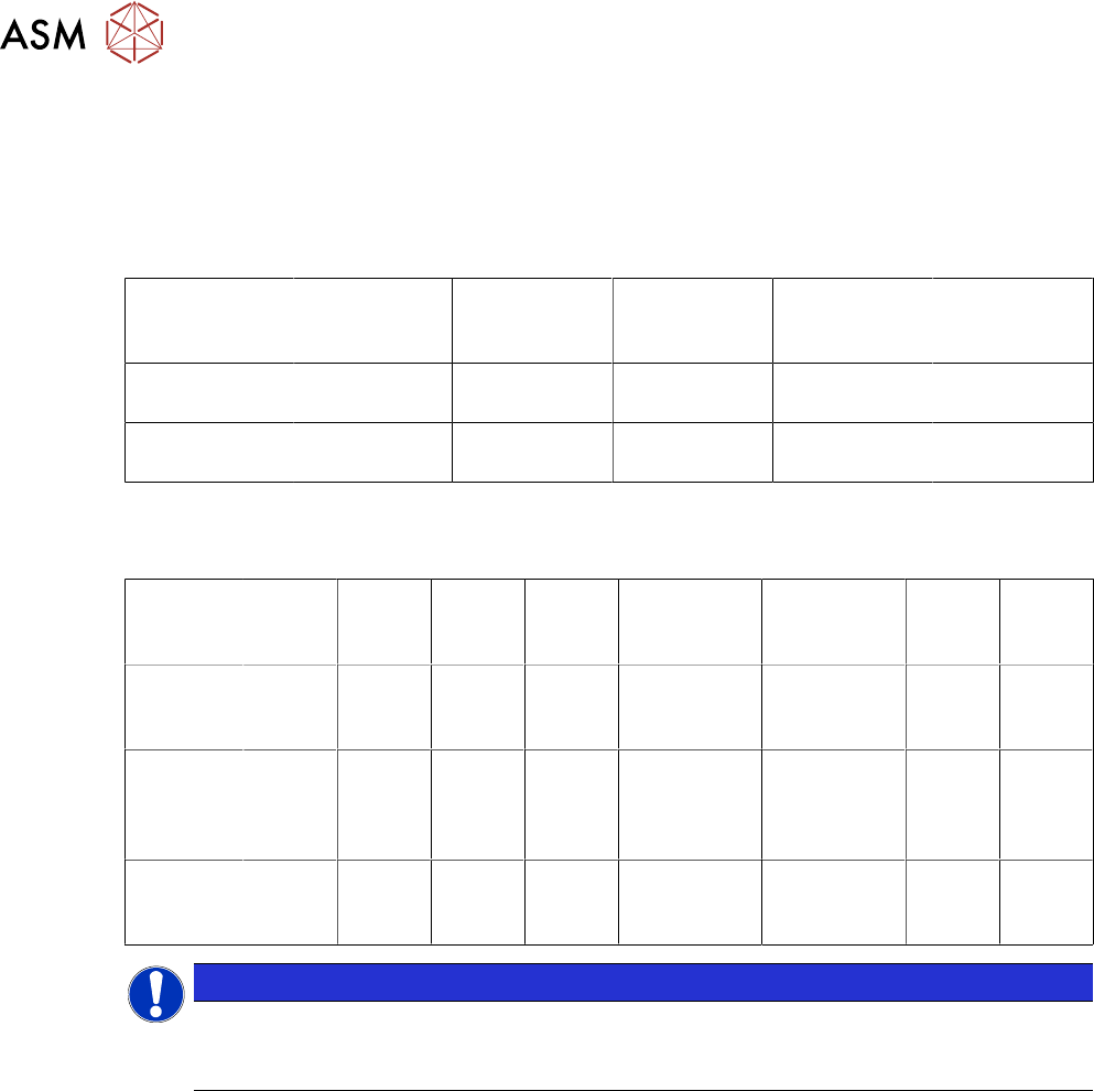
2.1.4.1 Table Positions
The table position required for the SIPLACE SX1/SX2 varies according to the head configuration:
SIPLACE SX1:
Gantry 1 C&P20P2 CPP_L CPP_H
without stat.
camera
CPP_H with
stat. camera
TH
Table position
location 1
Inner Inner Inner Outer Outer
Table position
location 2
Inner Inner Inner Inner Inner
SIPLACE SX2:
Gantry 1 C&P20
P2
CPP_L CPP_L C&P20
P2
CPP_H
with stat.
camera
CPP_H
with stat.
camera
TH TH
Table
position
location 1
Inner Inner Inner Inner Outer Outer Outer Outer
Gantry 2 C&P20
P2
CPP_L C&P20
P2
CPP_L CPP_H
with stat.
camera
CPP_H
without stat.
camera
CPP_H
with
stat.
camera
CPP_H
without
stat.
camera
Table
position
location 2
Inner Inner Inner Inner Outer Inner Outer Inner
NOTICE
CPP: only with stationary camera IC camera SST33
TH: with stationary camera IC camera SST33 at both locations, FC camera SST25 at loca-
tion 1 only
2 Brief Description
2.1 Overview
Assembly Instructions / Montageanleitung SIPLACE SX1/SX2 V3 Gantry Modularity Portalmodularität 05/2020 83
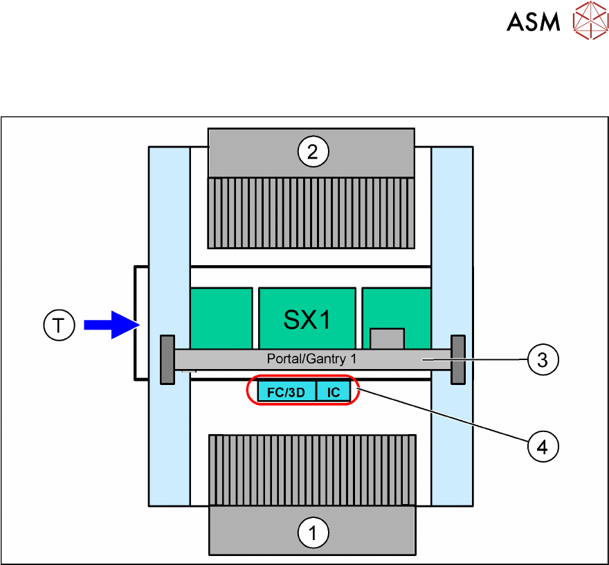
2.1.4.2 Stationary Cameras
SIPLACE SX1
Fig.7: Stationary cameras on the SIPLACE SX1
1. Location 1 in outer position
2. Location 2 in inner position
3. Gantry 1
4. IC camera and/or FC camera/3D coplanarity module (location1)
You can only install either an FC camera or a 3D coplanarity module!