00198705-01_AI_Portalmodularität_SX12_V3_DE_EN.pdf - 第76页
1 Introduction 1.4 Abbreviations 76 Assembly Instructions / Montageanleitung SIPLACE SX1/SX2 V3 Gantry Modularity Portalmodularität 05/2020 Do not allow modules with chargeable and highly insulating materials to touch on…
1 Introduction
1.3 Other instructions
Assembly Instructions / Montageanleitung SIPLACE SX1/SX2 V3 Gantry Modularity Portalmodularität 05/2020 75
1.3 Other instructions
1.3.1 Environmentally-friendly disposal of materials and components
Our products are manufactured using only materials and parts that can be easily separated and
disposed of in an environmentally-friendly way.
NOTICE
Observe the applicable regulations
The company operating the system has sole responsibility for the proper, environmentally-
friendly disposal of machines, working materials, consumable materials and wear parts.
► Please observe your national statutory provisions for waste disposal and environ-
mental protection.
1.3.2 Use of original accessories and spare parts
Only use original spare parts and authorized accessories. The use of other parts will affect safety
and will invalidate the liability for any consequential damage.
1.3.3 ESD guidelines
1.3.3.1 What does ESD mean?
Fig.3: ESD label
Almost all of the modules in use today are equipped with highly integ-
rated Metal-Oxide-Semiconductor (MOS) blocks and components.
The manufacturing techniques used mean that these electronic com-
ponents are extremely sensitive to overvoltage and thus to electro-
static discharge.
The abbreviation for such modules is "ESD" (Electrostatic Sensitive
Device). "ESD" is used internationally. The following symbol on cab-
inet rating plates, racks or packaging indicates that components
which are sensitive to electrostatic discharge have been used and
thus that the modules concerned are also touch-sensitive.
ESDs can be destroyed by voltages and power levels that are far below the level that can be per-
ceived by humans. Such voltages occur if a person touches a component or module without
earthing themselves. Components that are exposed to such overvoltages do not generally appear
to be defective immediately - incorrect behavior starts after the component or module has been in
operation for some time.
1.3.3.2 Important measures to protect against static charging
► Most plastics can easily become charged and must therefore be kept away from at-risk com-
ponents.
► Always ensure that people, the workplace and packaging are safely earthed when handling
electrostatic sensitive components.
1.3.3.3 Handling ESD modules
As a general rule: Only touch electronic modules if you must carry out work on the modules. In that
case, make sure that you do not touch the pins or printed conductors when you pick up flat mod-
ules.
Only touch components if you are earthed by one of the following measures:
●
You are wearing an ESD wristband.
●
You are wearing ESD shoes.
●
You are wearing ESD shoe earthing strips on an ESD floor.
Immediately before you touch an electronic module, discharge your own body by touching a con-
ductive and earthed object (such as unpainted parts of a switch cabinet, a water pipe, etc.).

1 Introduction
1.4 Abbreviations
76 Assembly Instructions / Montageanleitung SIPLACE SX1/SX2 V3 Gantry Modularity Portalmodularität 05/2020
Do not allow modules with chargeable and highly insulating materials to touch one another, e.g.
plastic films, insulating table surfaces or items of clothing made from synthetic fibers.
Always place the modules on a conductive surface (table with an ESD coating, conductive ESD
foam, ESD bag or container).
Do not move the assemblies near to data view devices, monitors or television units. Keep a min-
imum distance of 10 cm to monitors.
1.3.3.4 Measurements and modifications to ESD modules
Only perform measurements on modules if one of the following conditions is fulfilled:
●
You are using an earthed measuring device (e.g. via PE conductors).
●
You are using a potential-free measuring device and discharge the measuring head before
the measurement (e.g.by touching an unpainted metal part of the controller casing).
► Always use an earthed soldering iron if you carry out any soldering work.
1.3.3.5 Dispatching ESD modules
► Always store modules and components in conductive packaging (e.g. metallized plastic bags
or metal sleeves) and dispatch them in conductive packaging
► If the packaging is not conductive, place the modules in a conductive envelope before pack-
aging. Use conductive expanded rubber, ESD bags, domestic aluminum foil or paper, for
example. NEVER use plastic bags or film.
► If the module has integral batteries, ensure that the conductive packaging does not touch or
short circuit the battery terminals and, if necessary, first cover the terminals with insulating
tape or material.
1.3.4 Release History
Edition Amendments
05/2020 Initial release
1.4 Abbreviations
Abbreviation Description
PA Placement area
CO Component
COT Changeover table
COT-i Changeover table insert
C&P Collect&Place
C&P12, CP12 Collect&Place head with 12 segments
C&P20, CP20 Collect&Place head with 20 segments
C&P6, CP6 Collect&Place head with 6 segments
CoD Capacity on Demand
CPP Collect&Pick&Place head
CPx Collective term for CPP, CP20, CP12 and/or CP6
ESD Electrostatic sensitive device
EMC Electromagnetic compatibility
FHE Fast Hardware Exchange
LBO Long Board Option
PCB Board
P&P Pick&Place
TH TwinHead
2 Brief Description
2.1 Overview
Assembly Instructions / Montageanleitung SIPLACE SX1/SX2 V3 Gantry Modularity Portalmodularität 05/2020 77
2 Brief Description
These assembly instructions describe the installation and removal of a gantry as part of the gantry
modularity procedure for SIPLACE SX1/SX2 V3 machines.
2.1 Overview
This section provides an overview of the "Capacity on Demand" options for SIPLACE SX1/SX2
machines.
2.1.1 Machine Variants
SIPLACE Gantry configuration Description
SX+ Without gantry
"Add Feeder Slots"
The machine has been prepared for a gantry upgrade
(SX1), i.e. a trailing cable and one MGCU are prefitted for
one gantry.
SX+
prepared
Without gantry The machine has been prepared for a gantry upgrade
(SX1/2), i.e. two trailing cables and two MGCUs are prefit-
ted for two gantries.
SX1
unprepared
One gantry The machine has not been prepared for a gantry upgrade,
i.e. a trailing cable and one MGCU are prefitted for one
gantry. To upgrade to SX2, please contact your SIPLACE
Service team.
SX1
prepared
One gantry The machine has been prepared for a gantry upgrade
(SX2), i.e. two trailing cables and two MGCUs are prefitted
for two gantries.
SX2 Two gantries The machine can be downgraded to a SX1 prepared. It is
then prepared for a gantry upgrade to SX2, i.e. two trailing
cables and MGCUs are fitted.
2.1.2 Head Configuration
Various head configurations are possible. These vary according to the machine type used. Thereby
it is possible to fit the SIPLACE SX perfectly to the production requirements.
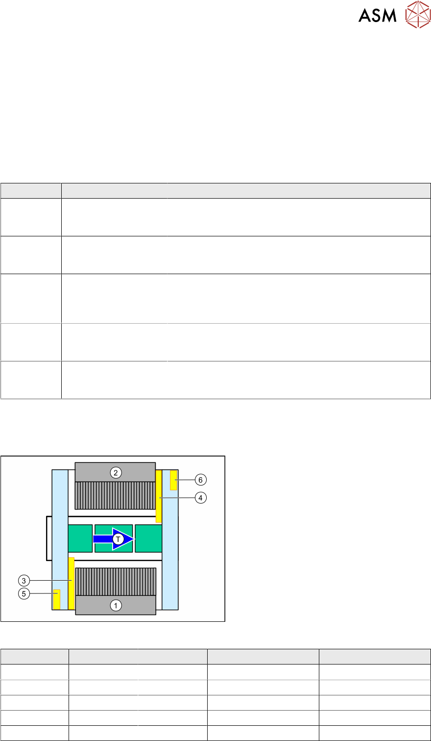
Fig.4: SIPLACE SX overview
1. Location 1 – inner position
2. Location 2 – inner position
3. Trailing cable gantry 1
4. Trailing cable gantry 2
5. MGCU 1
6. MGCU 2
T = transport direction
MGCU 1 MGCU 2 Trailing cable gantry 1 Trailing cable gantry 2
SX+ X - X -
SX+ prep. X X X X
SX1 X - X -
SX2 prep. X X X X
SX2 X X X X