00198705-01_AI_Portalmodularität_SX12_V3_DE_EN.pdf - 第111页
3 Fitting the Gantry 3.6 Final Work Assembly Instructions / Montageanleitung SIPLACE SX1/SX2 V3 Gantry Modularity Portalmodularität 05/2020 111 Fig.47: Gantry with TH->component mapping Confirming the autoconfigurati…
3 Fitting the Gantry
3.6 Final Work
110 Assembly Instructions / Montageanleitung SIPLACE SX1/SX2 V3 Gantry Modularity Portalmodularität 05/2020
3.6.6 Performing Calibration
NOTICE
Information about mapping
For details of mapping, such as the allocation of mapping plates to machine types, see the
technical information "Information about Mapping" [DE:TI2017‑10D04] [EN:TI2017‑10E04].
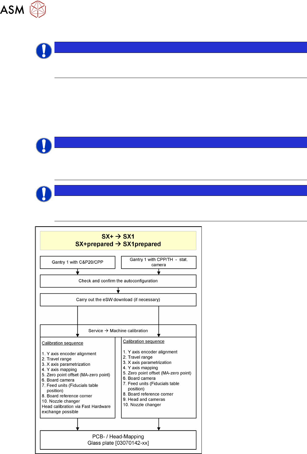
Overview
The calibration divides the mapping data and then merges them during the gantry upgrade. In most
cases this means that only a brief calibration procedure needs to be performed (see Fast Hardware
Exchange and flow diagram).
If gantry 1 is fitted, you need to perform PCB/component mapping with the glass plate, irrespective
of the head configuration (gantry 1 is the master gantry).
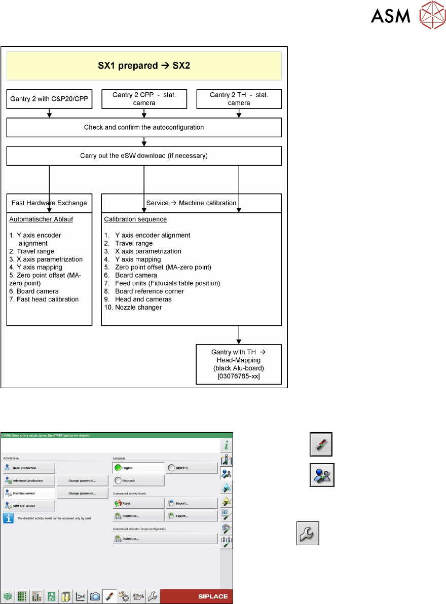
NOTICE
TwinHead gantry at location 2
If there is a TwinHead gantry fitted at location 2 (gantry 2), the PCB mapping data must be
present. Component mapping can then be performed using the aluminum plate. It is advis-
able to perform a complete PCB/component mapping!
NOTICE
Long Board Option (LBO)
If a gantry is installed on a machine with LBO, this gantry has to be mapped using the Map-
ping with LBO button.
Fig.46: PCB/component mapping
3 Fitting the Gantry
3.6 Final Work
Assembly Instructions / Montageanleitung SIPLACE SX1/SX2 V3 Gantry Modularity Portalmodularität 05/2020 111
Fig.47: Gantry with TH->component mapping
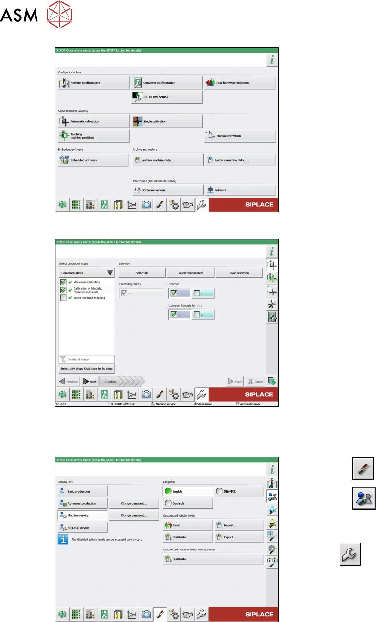
Confirming the autoconfiguration (SW 713.x)
Fig.48: Select operator level
► Select the button.
► Select the button.
► Switch over to the operator level Ma-
chine service.
ð The button will be shown.
3 Fitting the Gantry
3.6 Final Work
112 Assembly Instructions / Montageanleitung SIPLACE SX1/SX2 V3 Gantry Modularity Portalmodularität 05/2020
Fig.49: Service menu
► Select Automatic Calibration.
Fig.50: Calibration
► Go to Combined steps and select the
items Main axes calibration and Cali-
bration of fiducials, cameras and
heads.
► Select the gantry.
► Select Next and follow the instruction
on the screen.
3.6.6.1 eSW Download (SW 70x)
Fig.51: Select operator level
► Select the button.
► Select the button.
► Switch over to the operator level Ma-
chine service.
ð The button will be shown.