00198705-01_AI_Portalmodularität_SX12_V3_DE_EN.pdf - 第105页
3 Fitting the Gantry 3.5 Connecting the Trailing Cable Assembly Instructions / Montageanleitung SIPLACE SX1/SX2 V3 Gantry Modularity Portalmodularität 05/2020 105 Connections established Fig.39: Arranging the connection…
3 Fitting the Gantry
3.5 Connecting the Trailing Cable
104 Assembly Instructions / Montageanleitung SIPLACE SX1/SX2 V3 Gantry Modularity Portalmodularität 05/2020
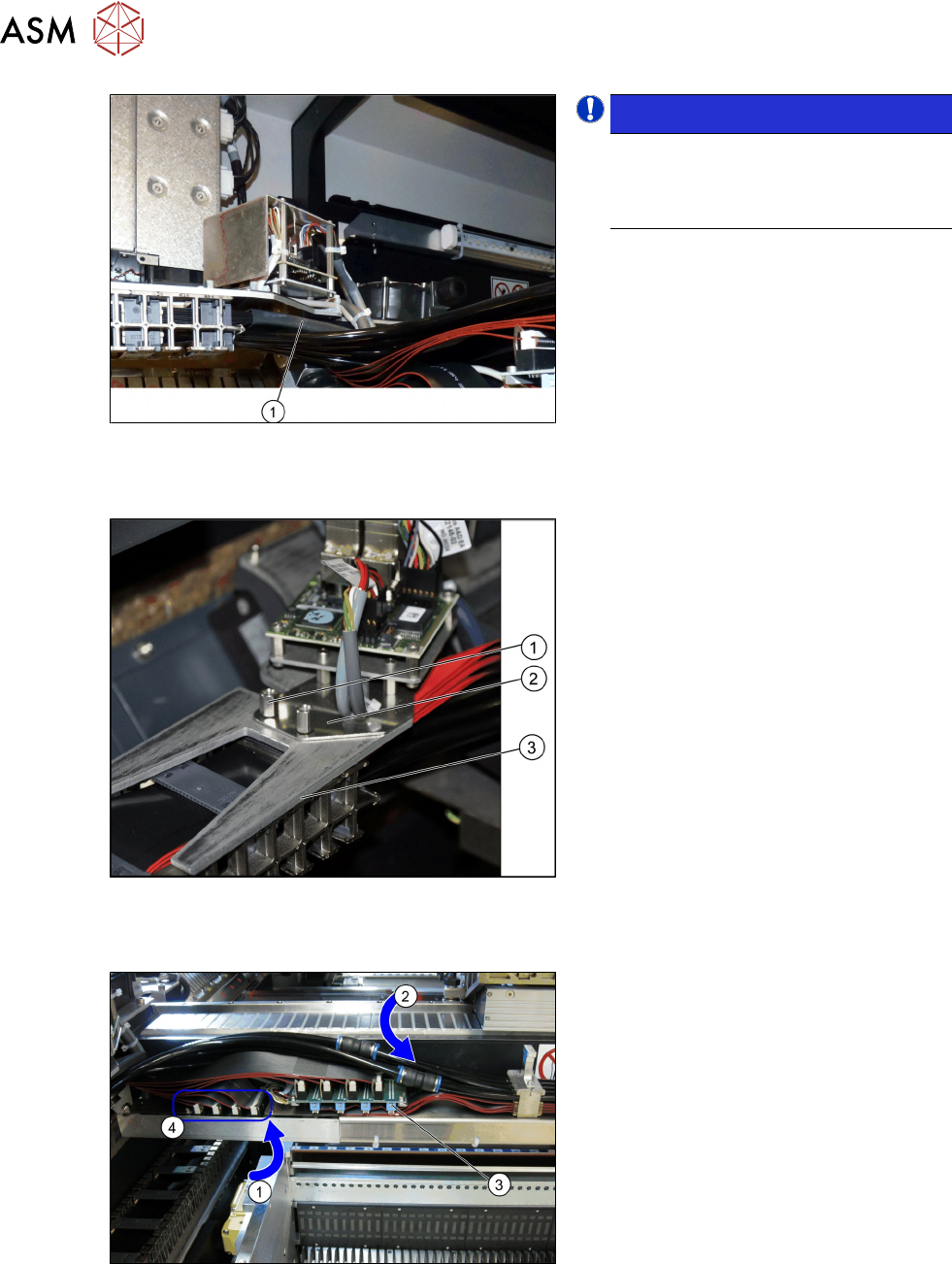
Fig.36: Heat-shrinkable hose
NOTICE!
When fitting the trailing cable, make
sure that the heat-shrinkable sleeve (1)
protects the flat ribbon cable under the
Y sensor module holder.
.
Trailing cable holder - overview
Fig.37: Trailing cable mount
1. Two hexagon spacer bolts M4 x 10 mm.
2. Gantry board holder
3. Trailing cable holder
► Remove the two hexagon spacer bolts
M4 x 10 mm on the trailing cable
holder.
► Hold the trailing cable holder from
below, on the gantry board holder.
► Screw the two hexagon spacer bolts
from above, into the trailing cable
holder.
► Secure the two hexagon spacer bolts
with Loctite 241.
Restore the electrical and pneumatic connections
Fig.38: Electrical and pneumatic connections
► First connect the seven flat ribbon
cables (1) to the boards for the gantry
interface of the X axis (3) and the
gantry interface of the Y axis (4). The
sequence depends on the different
cable lengths. Work your way from
back to front.
► Remove the dummy plugs from the
pneumatic hose couplings.
► Connect the four pneumatic connec-
tions for the trailing cable to the gantry
connections (2). The sequence de-
pends on the different hose lengths.
3 Fitting the Gantry
3.5 Connecting the Trailing Cable
Assembly Instructions / Montageanleitung SIPLACE SX1/SX2 V3 Gantry Modularity Portalmodularität 05/2020 105
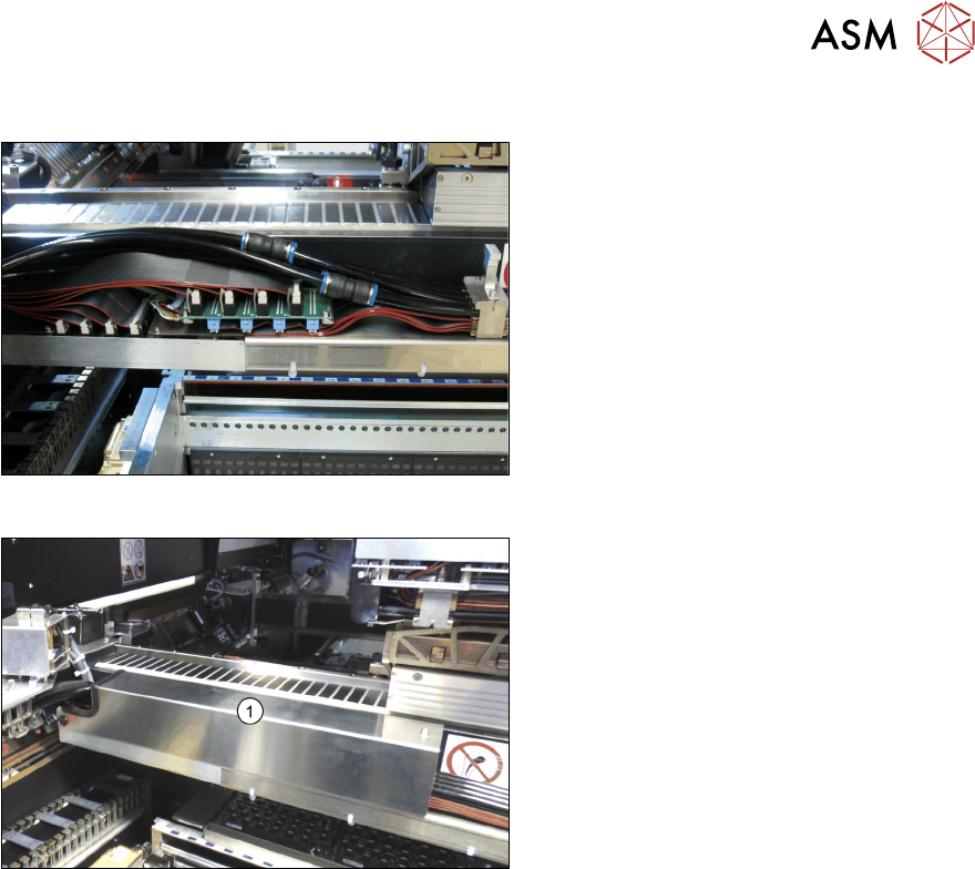
Connections established
Fig.39: Arranging the connections
This diagram shows the precisely run and
correctly arranged connections.
Fig.40: Fitting the cover
► Fit the cover (1) over the gantry inter-
face.
3 Fitting the Gantry
3.6 Final Work
106 Assembly Instructions / Montageanleitung SIPLACE SX1/SX2 V3 Gantry Modularity Portalmodularität 05/2020
3.6 Final Work
3.6.1 Stowing the Gantry Carrier and the Prepared Case
Stowing the gantry carrier in the transportation crate
► Use the gantry lift to move the gantry carrier into the transportation crate.
► Fix the gantry carrier into place in the transportation crate, with the four fastening screws.
► Release the gantry carrier from the gantry lift and move the gantry lift to one side.
► Place the foam cover for the placement head in the transportation crate.
► Close the front and top cover on the transportation crate.
Placing assembly parts in the "Prepared" case
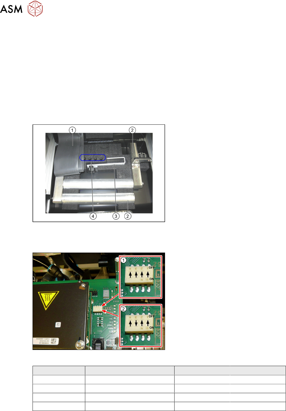
Fig.41: Prepared case
You have removed the following parts which
you will need to dismantle the gantry later
on. Keep these parts in the "Prepared" case:
1. Black plastic foil for trailing cable
2. The long end position buffer.
3. Trailing cable holder with knurled head
screw
4. Two transportation locks for the place-
ment head
●
A green lever as transportation lock for
the gantry
3.6.2 Checking the Gantry Coding
Fig.42: DIP switch gantry encoding for gantry 1 and 2
1. DIP switch for gantry 1
2. DIP switch for gantry 2
► Check the DIP switch for the gantry
coding of the locations on the head in-
terface.
Switch Designation Gantry 1 Gantry 2
1 DC/DC OFF OFF
2 FAN OFF OFF
3 P1 OFF ON
4 P0 OFF OFF