00198705-01_AI_Portalmodularität_SX12_V3_DE_EN.pdf - 第93页
3 Fitting the Gantry 3.2 Preparations at the Machine Assembly Instructions / Montageanleitung SIPLACE SX1/SX2 V3 Gantry Modularity Portalmodularität 05/2020 93 Loosening the trailing cable Fig.15: Taking the trailing ca…
3 Fitting the Gantry
3.2 Preparations at the Machine
92 Assembly Instructions / Montageanleitung SIPLACE SX1/SX2 V3 Gantry Modularity Portalmodularität 05/2020
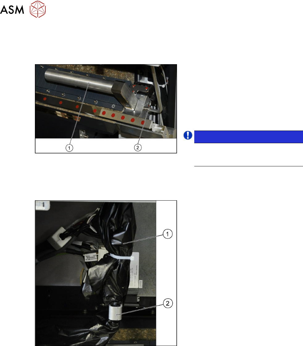
3.2.1 Removing the End Position Buffer
The long end position buffers must be fitted in SIPLACE SX1 machines with one gantry. These buf-
fers need to be removed and replaced with the short end position buffers in SIPLACE SX2
machines with two gantries.
Fig.13: End position buffer
Remove the two long end position buffers.
After fitting the second gantry, fit the two
short end position buffers in place of the
long ones.
► Loosen the fastening screw (2) on the
long end position buffer (1).
► Remove the two end position buffers
from the right and left sides.
NOTICE!
Keep the two long end position buffers
in the "Prepared" case for fitting back
into place later on.
.
3.2.2 Preparing the Trailing Cable
Overview
Fig.14: Trailing cable
The trailing cable (1) is packed in black
plastic foil and fixed to a holder(2).
3 Fitting the Gantry
3.2 Preparations at the Machine
Assembly Instructions / Montageanleitung SIPLACE SX1/SX2 V3 Gantry Modularity Portalmodularität 05/2020 93
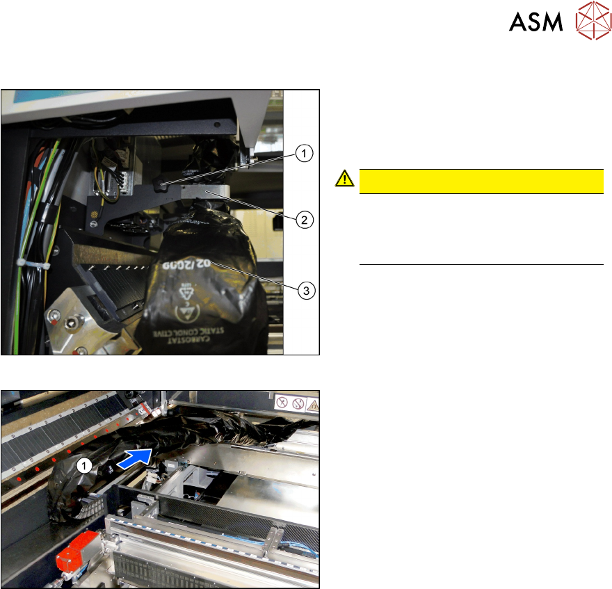
Loosening the trailing cable
Fig.15: Taking the trailing cable out of the holder
► Loose the fixture screw (1) on the
holder (2).
► Carefully disconnect the trailing cable
(3) from its holder.
CAUTION!
Take care when handling the trailing
cable!
Take care not to damage the foil or the
trailing cable.
.
► Place the holder and the fixture screw
in the "Prepared case" for fitting back
into place later on.
Fig.16: Trailing cable forwards in the machine
► Take the trailing cable (1) and place it
carefully towards the front, into the
machine.
3 Fitting the Gantry
3.3 Gantry Preparations
94 Assembly Instructions / Montageanleitung SIPLACE SX1/SX2 V3 Gantry Modularity Portalmodularität 05/2020
3.3 Gantry Preparations
The gantry is packed in a transportation crate. You need a gantry lift to transport the gantry.
3.3.1 The Gantry Lift
We recommend a gantry lift for transportation and assembly. Observe the following instructions:
WARNING
Installation
The installation can be performed manually, although we do recommend using a gantry lift
for safety purposes.
WARNING
Observe the manufacturer's operating guide!
Please consult the operating guide supplied for details of how to handle the gantry lift and
for all safety-relevant aspects. Observe the instructions therein
► Observe the safety instructions in the manufacturer's operating guide.
► Observe all safety instructions in this assembly guide when transporting and assem-
bling the gantry.
WARNING
Checks
► The operator is obligated to check the lifting assistance for visible damage at least
once at shift start or in case of an abnormality, anomaly or event and to give notice of
such damage immediately.
WARNING
Brake, wheels
► Lock the wheels by pushing the brake rod down/forward as far as possible before
loading or unloading the lifting assistance.
► Lock the foot brake after every moving procedure and/or after arriving the required
position in order to prevent inadvertent rolling of the lifting assistance. Release the
brake before moving it again.
WARNING
Stability, obstacles
► The platform must be always brought to the lowest position when using the lifting aid
as transportation unit (within the moving procedure). The load must always be
centered (in the center of gravity) on the platform (this may vary according to the indi-
vidual case) in order to achieve highest possible stability (tilt resistance) during mov-
ing. When moving the lifting aid, pay particular attention to obstacles such as door lim-
its, cables on the ground and also check the driving through height with the height of
the gantry lift slide. The small wheel diameter used (depends on configuration) could
mean that even smaller obstacles can cause an abrupt deceleration or inadvertent dir-
ection change if contact to the wheel is established.
► If the load is not completely lowered the lifting assistance may tilt or (in case of insuffi-
ciently secured load) the load may fall down depending upon driving speed and kind of
the obstacle. Thus, always lead the lifting assistance with appropriate speed, particu-
larly in curves and with changing or uneven soil conditions. Fasten the load always
sufficiently before transporting it in order to surely avoid inadvertent falling down and/
or reduce the transportation speed that also an unsecured load cannot glide from the
load pickup in case of an abrupt deceleration.
► Likewise the load must not come into oscillations during the transport . Thereby inad-
vertent reactions can occur.