Micron Technical Reference V9 Volume 1.pdf - 第171页
MACHINE CONTROL M36 MACHINE CONTROL ENCLOSURE Chapter Issue 12, Feb 18 Technical Reference Manual 7.27 M36SK24 (X Rear Actuator) M36SK25 (Y Actuator) M36PL26 (High Current DC In) Pin No. Signal Pin No. Signal 1C H 2 B - …
MACHINE CONTROL
M36 MACHINE CONTROL ENCLOSURE
7.26 Technical Reference Manual Chapter Issue 12, Feb 18
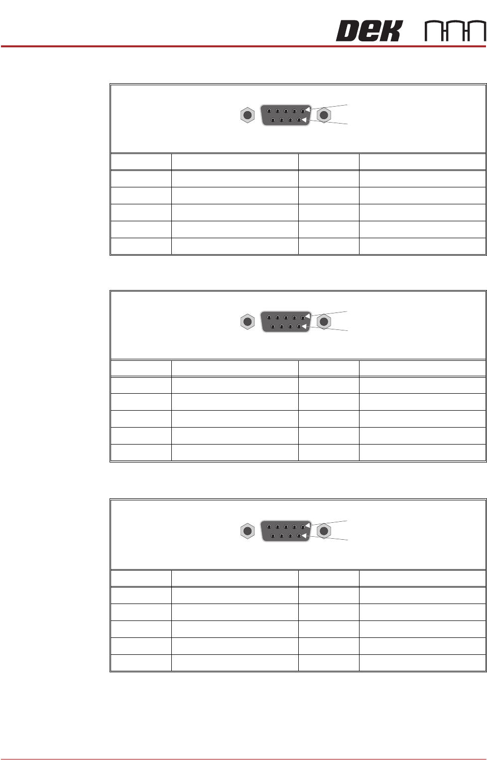
M36SK21 (Squeegee Motors)
M36SK22 (Moving Rail Motor)
M36SK23 (X Forward Actuator)
Pin No. Signal Pin No. Signal
1 CH1 B- 6 CH2 A-
2 CH2 B- 7 CH1 A+
3 CH1 B+ 8 CH2 A+
4CH2 B+ 9N/C
5CH1 A-
Pin No. Signal Pin No. Signal
1CH2 B- 6N/C
2N/C 7CH2 A+
3CH2 B+ 8N/C
4N/C 9N/C
5CH2 A-
Pin No. Signal Pin No. Signal
1CH1 B- 6N/C
2N/C 7CH1 A+
3CH1 B+ 8N/C
4N/C 9N/C
5CH1 A-
9 Way D Type Socket
1
6
9 Way D Type Socket
1
6
9 Way D Type Socket
1
6
MACHINE CONTROL
M36 MACHINE CONTROL ENCLOSURE
Chapter Issue 12, Feb 18 Technical Reference Manual 7.27
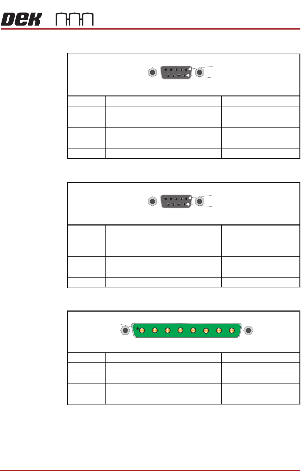
M36SK24 (X Rear Actuator)
M36SK25 (Y Actuator)
M36PL26 (High Current DC In)
Pin No. Signal Pin No. Signal
1CH2 B- 6N/C
2N/C 7CH2 A+
3CH2 B+ 8N/C
4N/C 9N/C
5CH2 A-
Pin No. Signal Pin No. Signal
1CH1 B- 6N/C
2N/C 7CH1 A+
3CH1 B+ 8N/C
4N/C 9N/C
5CH1 A-
Pin No. Signal Pin No. Signal
1 +12V 5 +24V US
20V Return 60V Return
3 +24V SW (Belt Motors) 7 +24V SW (Stepper Motors)
40V Return 80V Return
9 Way D Type Socket
1
6
9 Way D Type Socket
1
6
8 Way Power D Type Plug
1
MACHINE CONTROL
CAN BUS
7.28 Technical Reference Manual Chapter Issue 12, Feb 18
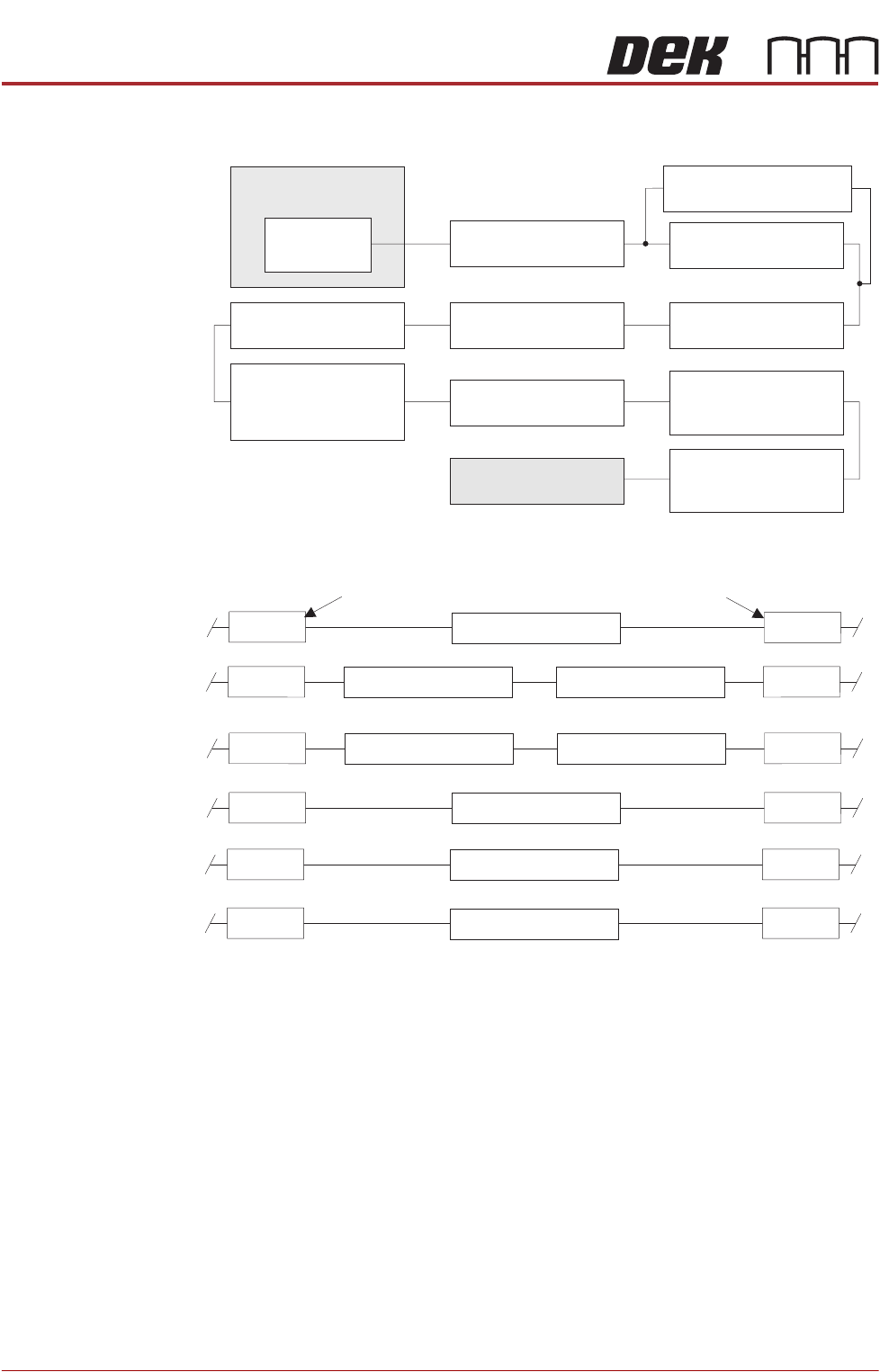
CAN BUS
Figure 7-6 CAN Bus
Figure 7-7 CAN Bus (Optional Rail Nodes)
The Controller Area Network (CAN) is a bus system for machine motion control.
An encoder/decoder for the 500Kbit/s rate CAN serial link is fitted to the
NextMove ES card to enable communication with the CAN Nodes. The CAN is
a 2-wire data link designed for transmission of small data packets for fast update
of axis position information.
The CAN Bus connects the NextMove ES card to the Nodes that provide
machine motion, switch functions and sensor feedback. There are two different
types of Nodes:
• I/O Node Boards
• Servo/Stepper Nodes
M36 Machine
Control Enclosure
NextMove ES
(I/O Node 1)
Stepper Node 10
Paste Dispense Motor
I/O Node 3 Board
Print Carriage I/O
Servo Node 7
Print Carriage Motor
I/O Node 2 Board
Main Machine I/O
I/O Node 4 Board
Screen Cleaner I/O
Various Nodes
depending on optional
rail system fitted
(see Rail Nodes Figure)
CAN Terminator
Servo Node 8
Camera X Motor
(Rotary Motors Only)
Servo Node 9
Camera Y Motor
(Rotary Motors Only)
Servo Node 6
Rising Table Motor
Servo Node 31
ProFlow Paste Condition
Node 2
Node 2
Node 2
Node 2
Node 2
Node 2
Node 4
Screen Clean IO
Part MMI
Node 4
Node 4
Node 4
Node 4
Node 4
Dual Lane Option
RTC Option (Left to Right)
RTC Option (Right to Left)
OTS/HTC Option
TRS Option
Thin Wafer Pallet
Stepper Node 15
Servo Node 11Stepper Node 12
Servo Node 16Stepper Node 12
I/O Node 5
I/O Node 19
I/O Node 17