Micron Technical Reference V9 Volume 1.pdf - 第239页
SQUEEGEE MODULE REPLACEMENT PROCEDURES Chapter Issue 6, Jul 16 Technical Reference Manual 9.11 Front Squeegee Drive Belt T o replace the front squeegee drive belt (left hand stepper motor), the printhead mechanism must b…
SQUEEGEE MODULE
REPLACEMENT PROCEDURES
9.10 Technical Reference Manual Chapter Issue 6, Jul 16
and remove the broken drive belt.
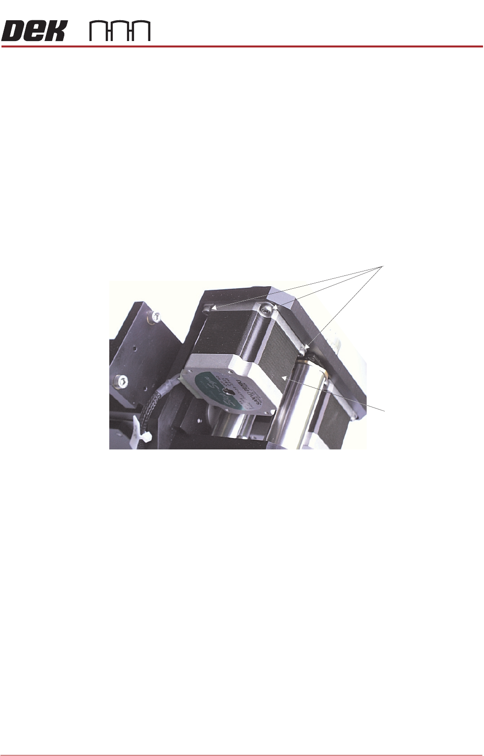
NOTE
In the drive belt replacement procedures, described below, the tensioning of the
belt only applies where the squeegee stepper motors are identified by the green
label shown in figure 9-3. For all other squeegee types, follow the ‘Alternative
Drive Belt Replacement’ procedure.
Rear Squeegee
Drive Belt
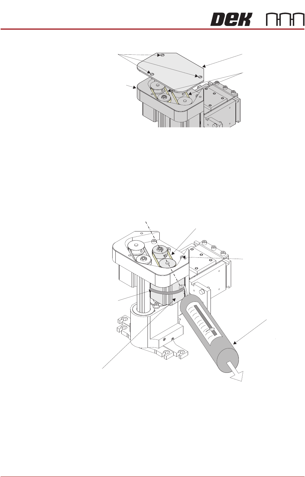
The rear squeegee drive belt (right hand stepper motor) can be replaced without
having to remove the printhead mechanism from the print carriage.
1. Slacken off the three screws securing the right hand motor to the motor
support plate.
2. Fit the new belt in position.
3. Using a cable tie wrap or similar, provide a loop around the top of the body
of the motor enabling the motor to be pulled using a force meter. Ensure
that the force meter is pulled in the direction which the drive belt is fitted,
figure above refers.
4. Pull the force meter until a tension of 3-4kgs is monitored on the meter.
Tighten the three screws whilst the motor is under tension.
Drive Belt Cover Plate
Drive Belts
Squeegee Printhead
Mechanism
Securing Screws
Tension in Direction of
Drive Belt Orientation
Right Stepper Motor
Rear Squeegee Motor Tensioning
Force Meter
Motor Securing Screw
Position (3 positions)
Looped CableTie
Drive Belt
SQUEEGEE MODULE
REPLACEMENT PROCEDURES
Chapter Issue 6, Jul 16 Technical Reference Manual 9.11
Front Squeegee
Drive Belt
To replace the front squeegee drive belt (left hand stepper motor), the printhead
mechanism must be removed from the print carriage.
1. Disconnect the following connectors from the print carriage, left hand side.
• Rear Squeegee Motor
• Front Squeegee Motor
• Home Sensors
• Squeegee Pressure Amplifier
2. Remove the printhead mechanism by unscrewing the four screws securing
the unit to the print carriage.
3. Placing the unit on a secure surface, slacken off the three screws securing
the left hand motor to the support plate.
Figure 9-3 Squeegee Stepper Motor (Green Ident Label Shown)
4. Fit the new belt in position.
5. Using a cable tie wrap or similar, provide a loop around the top of the body
of the motor enabling the motor to be pulled using a force meter. Ensure
that the force meter is pulled in the direction which the drive belt is fitted,
Rear Squeegee Motor Tensioning figure example refers.
6. Pull the force meter until a tension of 3-4kgs is monitored on the meter.
Tighten the three screws whilst the motor is under tension.
7. On completion re-fit the printhead mechanism to the print carriage refit the
drive belt cover plate and re-connect all leads to the print carriage, left hand
side.
8. Refit the squeegees.
Stepper Motor
Securing Screws
Front Squeegee
Motor
SQUEEGEE MODULE
REPLACEMENT PROCEDURES
9.12 Technical Reference Manual Chapter Issue 6, Jul 16
Alternative Drive
Belt Replacement
This replacement procedure applies to both front and rear belts. It is advised
that drive belts are replaced as a pair.
NOTE
1. If the underside of the stepper motors has a green ident label this procedure
does not apply;refer to figure 9-3.Follow the previous procedures for belt
replacements.
2. The pulley hole centres are fixed. There is no need for pulley belt tension
adjustment.
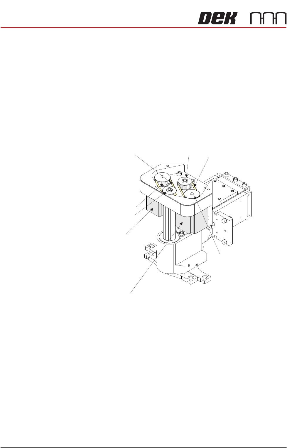
The squeegee drive belts can be replaced without having to remove the
printhead mechanism from the print carriage.
1. Pull the drive belt from its centre and slip it up over the idler pulley.
2. Slip the belt over the drive pulley and discard it.
3. Repeat Steps 1 and 2 for the other belt.
4. Hold the new belt in position. Align the teeth of the drive pulley with the teeth
of the belt and engage the belt on the pulley.
5. Whilst maintaining light tension on the belt in the drive pulley, to prevent it
from slipping off, rotate the idler pulley to align its teeth with the belts’ teeth.
6. Slip the belt down over the idler pulley; rotate the idler pulley if necessary to
aid fitment and alignment.
NOTE
Even with power removed the drive pulley does not rotate.
7. Repeat Steps 4-6 for the other belt.
8. On completion refit the drive belt cover plate and re-connect all leads to the
print carriage, left hand side.
9. Refit the squeegees.
R Stepper Motorear
Front Stepper Motor
Squeegee Motor Belt Replacement
Rear Drive BeltIdler Pulley
Idler Pulley
Drive Pulley
Drive Pulley
Front Drive Belt