Micron Technical Reference V9 Volume 1.pdf - 第280页
PROFLOW MODULE ADJUSTMENTS AND SETTINGS 11.6 Technical Reference Manual Chapter Issue 2, Aug 14 ADJUSTMENTS AND SETTINGS ProFlow Paste Level Sensor There is no adjustment and setting for this sen sor . ProFlow Stencil Su…
PROFLOW MODULE
ELECTRICAL SCHEMATIC
Chapter Issue 2, Aug 14 Technical Reference Manual 11.5
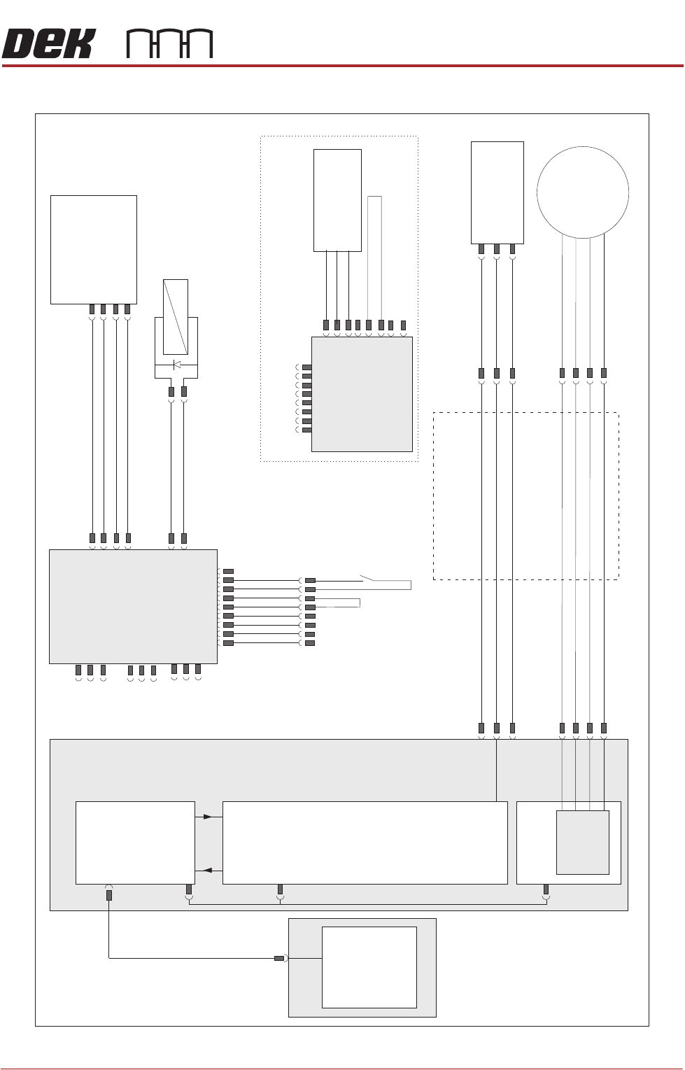
ELECTRICAL SCHEMATIC
ProFlow
Fitted Link
Motor 2 B-
Motor 2 B+
Motor 2 A-
Motor 2 A+
Print Carriage
Drag Chain
9PL08
9PL17
Print Carriage I/O
Node 3
N3PL13
N3PL17
N3SK2
N3SK1
N3SK3
N3PL8
9SK25
NextMove ES
(I/O Node 1)
NextMove
Interface
Dual Stepper
Card X2
M36 Machine Control
PC
Motherboard
Step 4
M36PL12
M36PL21
CAN
In
CAN
Out
Node Power
Stepper
Motor
(9M4)
ProFlow
Home
(9SE05)
+12V
0V
Signal
Pneumatic
Valve
(9S0L25)
+
-
+24V
Monitor O/P
I/P Signal
0V
ProFlow Pressure
Regulator
M18SK02
+12V
0V
Signal
Paste
Level
(9SE25)
ProFlow Paste
Level Amplifier
19
9SK61
9SK61
ProFlow
Fitted
Link
Cassette Low
9PL62
ProFlow ‘Time To Go
Option’
USB 4
3PL35
M36PL28

PROFLOW MODULE
ADJUSTMENTS AND SETTINGS
11.6 Technical Reference Manual Chapter Issue 2, Aug 14
ADJUSTMENTS AND SETTINGS
ProFlow Paste
Level Sensor
There is no adjustment and setting for this sensor.
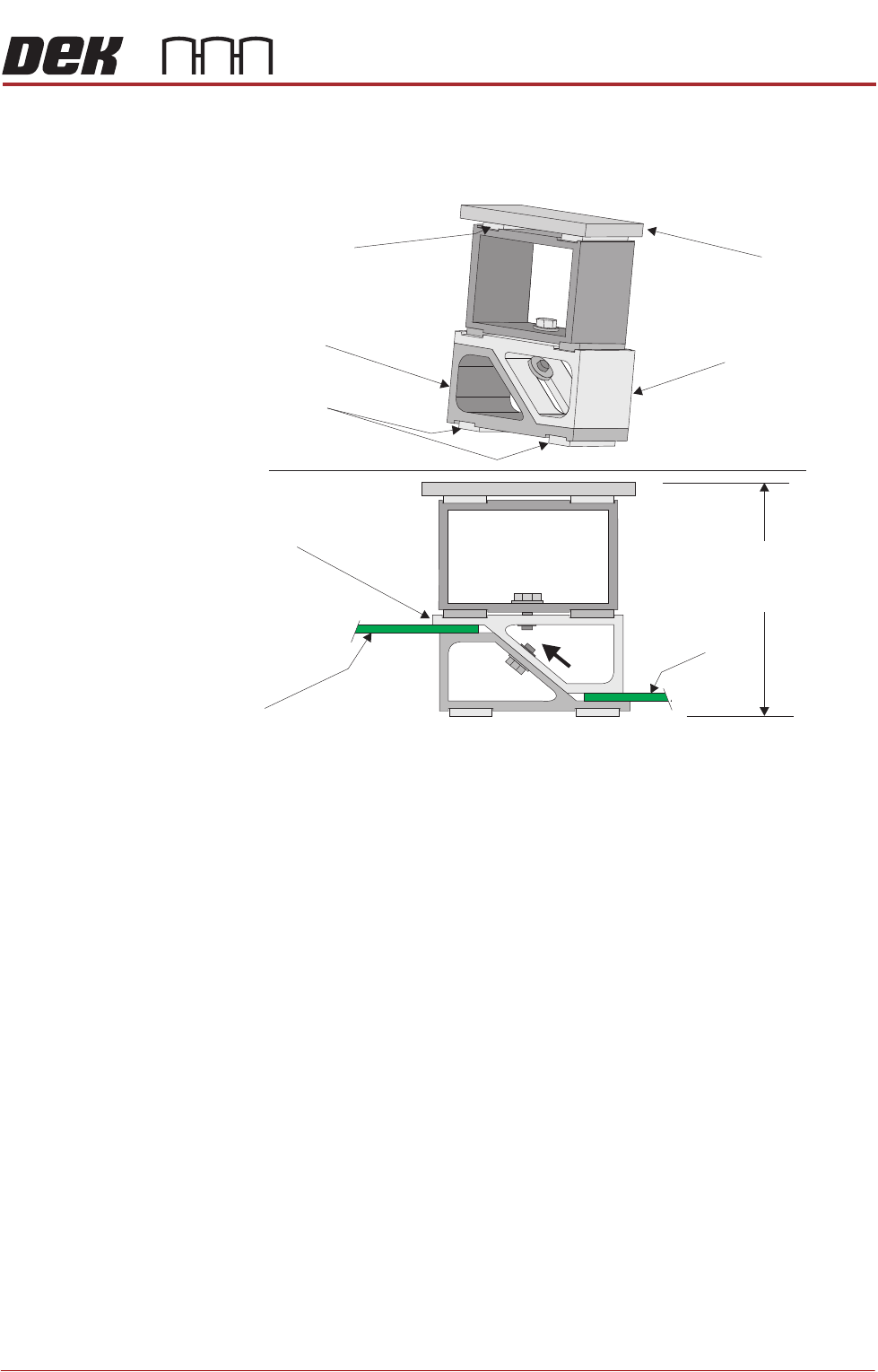
ProFlow Stencil
Support
The ProFlow stencil support option provides stencil support when printing
boards that are narrower than the ProFlow transfer head, thus avoiding poten-
tial paste smearing onto the top of the stencil and stabilising the pressure within
the transfer head.
The standard height when the adjustable tooling top is in the closed position is
81mm. The support comprises the following items:
• Changeable Gauge Plate
• Tooling Bottom
• Adjustable Tooling Top
NOTE
Refer to Board Support Tooling chapter of this manual for further information.
PROFLOW MODULE
ADJUSTMENTS AND SETTINGS
Chapter Issue 2, Aug 14 Technical Reference Manual 11.7
Height Adjustment To set the ProFlow stencil support to the correct height carry out the following:
1. Loosen the 7mm hexagonal nut securing the adjustable tooling top and the
tooling bottom.
2. Slide the adjustable tooling top upwards to open up the tooling top and
bottom faces.
3. Position two printed circuit boards to be printed between the adjustable
tooling top and tooling bottom opening faces.
4. Tighten the bolt locking the adjustable tooling top to the tooling bottom.
5. Remove both printed circuit boards.
The support is now set to the correct stencil height, ie 81mm + thickness of
board.
Changeable
Gauge Plate
Tooling Bottom
Magnetic Feet
Magnetic Support
(2 positions)
Adjustable Tooling
Top
Board
Adjustable
Tooling Top
Board
Stencil Support
Height (81mm +
PCB Thickness)