Micron Technical Reference V9 Volume 1.pdf - 第288页
PROFLOW MODULE CALIBRATIONS 11.14 Technical Reference Manual Chapter Issue 2, Aug 14 CALIBRA TIONS ProFlow Contact Position Setup T o set up the ProFlow contact height posit ion carry out the following procedure: 1. Sele…
PROFLOW MODULE
REPLACEMENT PROCEDURES
Chapter Issue 2, Aug 14 Technical Reference Manual 11.13
11. Loosen the four captive screws securing the ProFlow printhead mechanism
to the print carriage using a 4mm Allen key. Carefully remove the mecha-
nism from the print carriage.
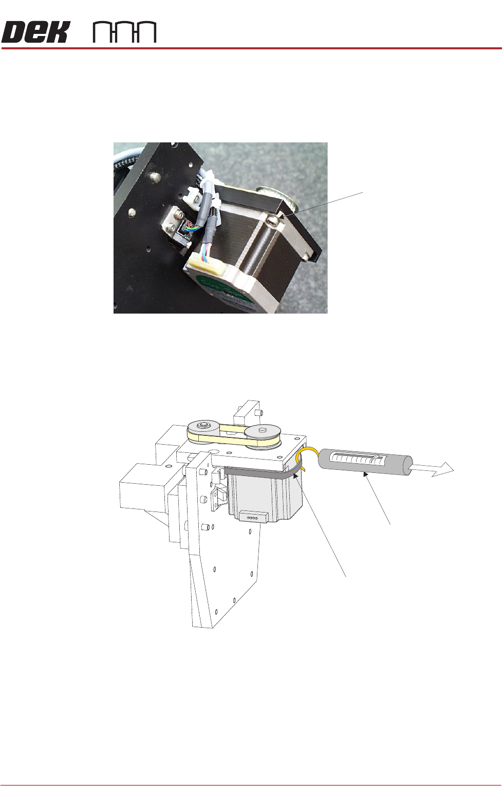
12. Placing the unit on a secure surface, slacken off the four screws securing
the stepper motor to the support plate.
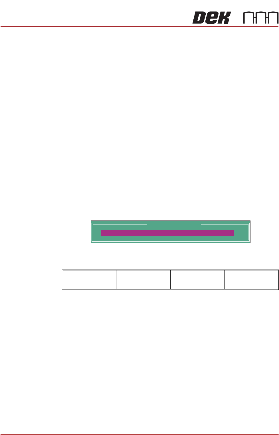
13. Remove the old belt and fit the new belt in position.
14. Using a cable tie wrap or similar, provide a loop around the top of the motor
body enabling the motor to be pulled using a force meter. Ensure that the
force meter is pulled in the direction which the drive belt is fitted.
15. Pull the force meter until a tension of 3kgs to 4kgs is monitored on the
meter. Tighten the four screws whilst the motor is under tension.
16. On completion re-fit the printhead mechanism to the print carriage and re-
connect all leads to the print carriage.
17. Re-fit pressure mechanism and transfer head to printhead mechanism.
Motor Securing Screws
(4 positions)
Force Meter
Tie-wrap
3kgs to 4kgs
Tension
PROFLOW MODULE
CALIBRATIONS
11.14 Technical Reference Manual Chapter Issue 2, Aug 14
CALIBRATIONS
ProFlow Contact
Position Setup
To set up the ProFlow contact height position carry out the following procedure:
1. Select Open Cover Commands.
2. Select Carriage To Front.
3. Select Back.
4. Open the front printhead cover.
5. Load the calibration stencil into the chase.
6. Fit an empty transfer head to the ProFlow pressure mechanism and remove
the ProFlow cover.
7. Position a 0.1mm shim on the stencil under the transfer head.
8. Close the front printhead cover.
9. Press the System button.
10. Select Load Screen.
11. Select Maintenance.
12. Select Calibrations.
13. Select ProFlow.
14. Select ProFlow Heights.
The following window and menu bar is displayed:
This parameter sets the height of the ProFlow printhead so that it just
touches the stencil surface.
15. Using the Incr. or Decr. keys, set the Contact Position to 5.5mm.
16. Select Move to Position, the ProFlow unit is driven to the position set.
17. Open the front printhead cover.
NOTE
Correct contact height is when the shim is just held between the transfer
head wipers and stencil. At this position it is not possible to slide the shim
sideways past the transfer head skis.
18. If correct contact height is achieved go to Step 24.
19. Close the front printhead cover.
20. Press the System button.
21. Using the Incr. or Decr. buttons, increase or decrease the Contact Position
set height by 0.5mm (eg 5.0mm or 6.0mm).
NOTE
Normally the contact position is between 4mm and 8mm (nominally 6mm).
Minimum Maximum Increment Default
- 10mm +10mm 0.1mm 0.0mm
ProFlow Calibrations
PFLOW CONTACT POS.
0.0
mm

PROFLOW MODULE
CALIBRATIONS
Chapter Issue 2, Aug 14 Technical Reference Manual 11.15
22. Select Move to Position, the ProFlow unit is driven to the position set.
23. Repeat Steps 17 to 22 to vary the set position until the correct contact height
is achieved.
24. Close the front printhead cover.
25. Press the System button.
26. Select Exit.
27. Select Exit.
28. Select Exit.
29. Select Back.
30. Select Unload Screen.
31. Open the front printhead cover.
32. Remove the shim
33. Remove empty transfer head.
34. Remove calibration stencil.
35. Close the front printhead cover.
36. Press the System button.
ProFlow Transfer
Material
To set up the ProFlow sensor, carry out the following procedure:
1. Select Open Cover Commands.
2. Select Carriage To Front.
3. Select Back.
4. Open the front printhead cover.
5. Ensure that the correct product stencil is fitted.
6. Fit an empty transfer head to the ProFlow pressure mechanism and remove
the ProFlow cover.
7. Close the front printhead cover.
8. Press the System button.
9. Select Maintenance.
10. Select Calibrations.
11. Select ProFlow.
12. Select Transfer Material.
13. Select Set Empty.
14. The following message is displayed:
‘Confirm: Transfer head is fitted and empty?’
15. Select Confirm.
16. If prompted confirm that the correct stencil is fitted.
17. If prompted confirm that the correct ProFlow head size is fitted.
18. The following message is displayed:
‘The ProFlow unit will be placed at the rear of the image’