Micron Technical Reference V9 Volume 1.pdf - 第269页
PROACTIV REPLACEMENT PROCEDURES Chapter Issue 5, Jan 15 Technical Reference Manual 10.19 REPLACEMENT PROCE DURES Fitment NOTE The ProActiv option cannot be used if a squeegee drip tray is fitted to the printer . Remove t…

PROACTIV
ADJUSTMENTS AND SETTINGS
10.18 Technical Reference Manual Chapter Issue 5, Jan 15
Setting the Proximity
Switches
Ensure that squeegee pressure and squeegee reference height calibrations
have been completed before proceeding.
1. Select Setup Product.
2. Select Squeegees.
3. Ensure that Dwell Height is set to the default value of 30mm.
4. Select Back.
5. Select Save.
6. Select Back.
7. Select Maintenance.
8. Select Diagnostics.
9. Select the Squeegee from the Module Diagnostic Page list.
10. Select Home Front Squeegee.
11. Select Run Diagnost.
12. Select Home Rear Squeegee.
13. Select Run Diagnost.
14. Select Front Squeegee To Dwell Height.
15. Select Run Diagnost.
16. Select Drive Front Squeegee Using Jog Buttons.
17. Drive the squeegee down by approximately 2mm.
18. Use a flat bladed trimmer to adjust the front squeegee proximity sensor
until the sensor light is OFF.
19. Drive the squeegee back to Dwell Height; ensure the light is ON.
20. Repeat Step 6; ensure the light is OFF.
21. Repeat Steps 3 through 9 for the rear squeegee.
22. Select Exit.
23. Select Exit.
24. Select Back.

PROACTIV
REPLACEMENT PROCEDURES
Chapter Issue 5, Jan 15 Technical Reference Manual 10.19
REPLACEMENT PROCEDURES
Fitment NOTE
The ProActiv option cannot be used if a squeegee drip tray is fitted to the printer.
Remove the squeegee drip tray before fitting the active squeegee module to the
printer. Do not attempt to fit a squeegee drip tray to a printer, which has a
ProActiv module fitted.
Figure 10-2 The Warning Label as Fitted to the Active Squeegee Set
This procedure details the fitment of the ProActiv unit to the printer.
1. From the Ready page select Open Cover Commands.
2. Select Carriage to Front.
3. Select Back.
4. Select Shut Down.
5. Select Confirm.
6. Turn the mains isolator to the OFF position.
7. Open the printhead front cover.
8. Remove the stencil.
9. Remove any applicator modules fitted to the printhead mechanism; refer to
the relevant chapter of this manual or the module’s stand alone manual.
NOTE
The ProActiv option cannot be used if a Squeegee Drip Tray is fitted to the
printer. Remove the paste drip tray before fitting ProActiv active squeegee
module to the printer. Do not attempt to fit a paste drip tray to a printer which
has a ProActiv module fitted.
10. Place a board over the rails at the tooling area; this is used to support the
squeegee mechanism.
WARNING!
Squeegee Drip tray MUST be removed when using ProActiv
.Squeegees Only use Drip tray with Standard Squeegees.
ATTENTION!
Le plateau sous racles DOIT ętre retiré quand les racles ProActiv
sont utilisées. Le plateau sous racles ne peut ętre utilisé qu'avec
des racles standard.
WARNUNG!
Das Abtropfblech der Rakel MUSS entfernt Werden, falls die
ProActiv Rakel verwendetwerden. Das Abtropfblech darf nur mit
Standard Rakel verwendet werden.
PROACTIV
REPLACEMENT PROCEDURES
10.20 Technical Reference Manual Chapter Issue 5, Jan 15
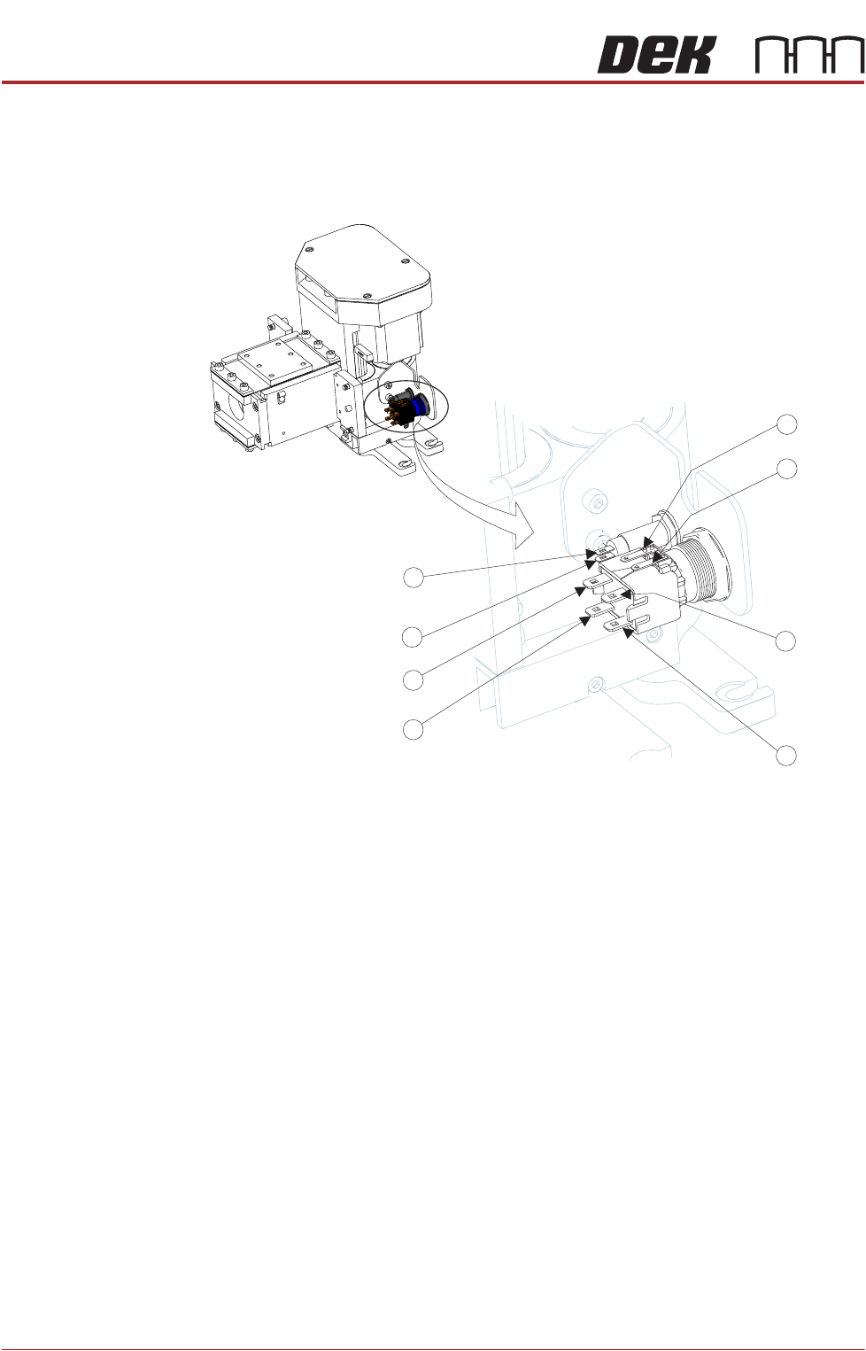
11. Place the squeegee mechanism on the board.
12. On the squeegee mechanism, connect the four spade connectors to the
enable switch /indicator and the two spade connectors to the status indicator
from N18PL08 (6) and N18PL05 (2) as follows:
Enable switch/indicator.
• Grey lead to Pin 1.
• Violet lead to Pin 2.
• No connection Pin 3.
• No connection Pin 4.
• Red lead to Pin 5 (marked +).
• Black lead to Pin 6 (marked -).
Status indicator.
• Brown lead to Pin 1 (Identified by the red dot on the indicator body.)
• White lead to Pin 2.
5
6
3
2
1
4
2
1
Status
Status
Enable
Enable
Enable
Enable
Enable
Status
Enable
Status