SIPLACE S-23 HM.pdf - 第67页
User Manual SIPLAC E S-23 HM 2 Operational Safety Software Version SR.406.xx 02/00 US Edition 2.1 Safety instructions 67 2.1.8 Safety instructions for coupling and uncoupling the mobile changeover ta b le W ARNING 2 Å Ne…
2 Operational Safety User Manual SIPLACE S-23 HM
2.1 Safety instructions Software Version SR.406.xx 02/00 US Edition
66
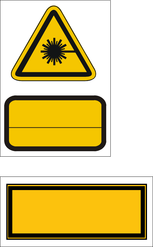
Laser radiation 2
The radiation from the laser diode (infrared or IR
light) of the PCB barcode reader is harmful to the hu-
man eye, 2
Åso you should never look into the laser beam.
ÅNever direct the PCB barcode reader into other
people’s eyes,
ÅWhen installing the barcode reader, make sure
that the laser beam cannot be not reflected dur-
ing use.
If you open the housing during use, the scanning cy-
cle will continue and the laser diode will continue to
switch on. 2
The laser beam output at the barcode template win-
dow does not exceed 1.0 mW. The PCB barcode
reader thus conforms to protection class 2. 2
Fig. 2.1 - 6 ‘Laser radiation’ label
2
2
2
2
2
2
Fig. 2.1 - 7 ‘Caution …’ label
2
LASER RADIATION
DO NOT LOOK INTO BEAM
CLASS 2 LASER PRODUCT
EN 60825 1991
Max. output radiation: 1.0 mW
Emitted wave length: 670 nm
ATTENTION
Caution
Laser radiation when the cover is opened
and the safety interlock is bypassed
Do not look into the beam
User Manual SIPLACE S-23 HM 2 Operational Safety
Software Version SR.406.xx 02/00 US Edition 2.1 Safety instructions
67
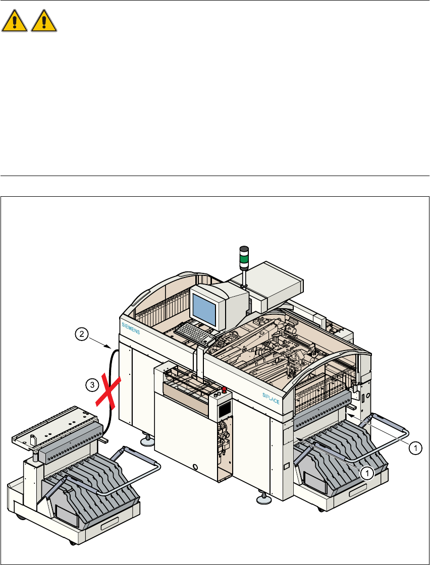
2.1.8 Safety instructions for coupling and uncoupling the mobile changeover
table
WARNING 2
Å Never reach into the gaps between the component changeover table and the placement sys-
tem frame while the machine is running (item 1).
Å Always check that the component table is docked on the placement system before connecting
or disconnecting the power cable for the component changeover table at the socket on the
placement system (item 2).
Å NEVER connect the connecting cable for the component table to the socket on the placement
system and then operate the component table outside the machine via the compressed air
control unit (item 3).
Fig. 2.1 - 8 Safety instructions for coupling and uncoupling the mobile changeover table

2 Operational Safety User Manual SIPLACE S-23 HM
2.1 Safety instructions Software Version SR.406.xx 02/00 US Edition
68
6DIHW\LQVWUXFWLRQVIRUFKDQJLQJWKHKHL JKWRIFRPSRQHQWWDEOH V
WARNING 2
The component table must only be converted to modify the default
height by trained Service personnel.
Act with considerable care during the conversion process since
the system contains large weights or compression springs (potential
energy).
&RQYHUWLQJWKHFRPSRQHQWWDEOHWRVXLWDGLIIHUHQWOLQHKHLJKW
Å Use the placement system’s pneumatic controller to raise the table bed. Then insert a 120mm
spacer block between the table bed and cross-beam, and lower the bed onto the block.
Å Dismantle the internal paneling.
Å Swivel the handle down. The latching disk swivels down as well.
Å Set the screw to the desired dimension and lock in place with the locknut.
3/($6(127(
,I\RXFDQQRWORRVHQWKHDGMXVWLQJVFUHZIDUHQRXJKWKHFURVVEHDPPXVWEHUDLVHG
Å Fix the lifting device to the cross-beam.
Å
Carefully
open the cross-beam clamp.
Å Raise the cross-beam until the end of the tube projects approx. 1mm out of the clamp.
Å Tighten the cross-beam clamp.
Å Then turn the adjusting screw to the desired dimension and lock in place with the locknut.
Å Swivel the component table handle up. The latching disk will also swivel up.
3/($6(127(
,I\RXFDQQRWVZLYHOWKHODWFKLQJGLVNXSWRLWVHQGSRVLWLRQWKHFURVVEHDPPXVWEHUDLVHG
Å )L[WKHOLIWLQJGHYLFHWRWKHFURVVEHDP
Å &DUHIXOO\RSHQWKHFURVVEHDPFODPS
Å 5DLVHWKHFURVVEHDPXQWLOWKHHQGRIWKHWXEHSURMHFWVDSSUR[PPRXWRIWKHFODPS
Å 7LJKWHQWKHFURVVEHDPFODPS
Å Then turn the adjusting screw to the desired dimension and lock in place with the locknut.