SIPLACE S-23 HM.pdf - 第84页
2 Operational Safety User Manual SIPLACE S -23 HM 2.3 Residual voltages i n the servo unit and discharge times Software Version SR.406.xx 02/00 US Edition 84 2.3 Res idual voltages in the se rvo unit and dischar ge time …
User Manual SIPLACE S-23 HM 2 Operational Safety
Software Version SR.406.xx 02/00 US Edition 2.2 Safety equipment
83
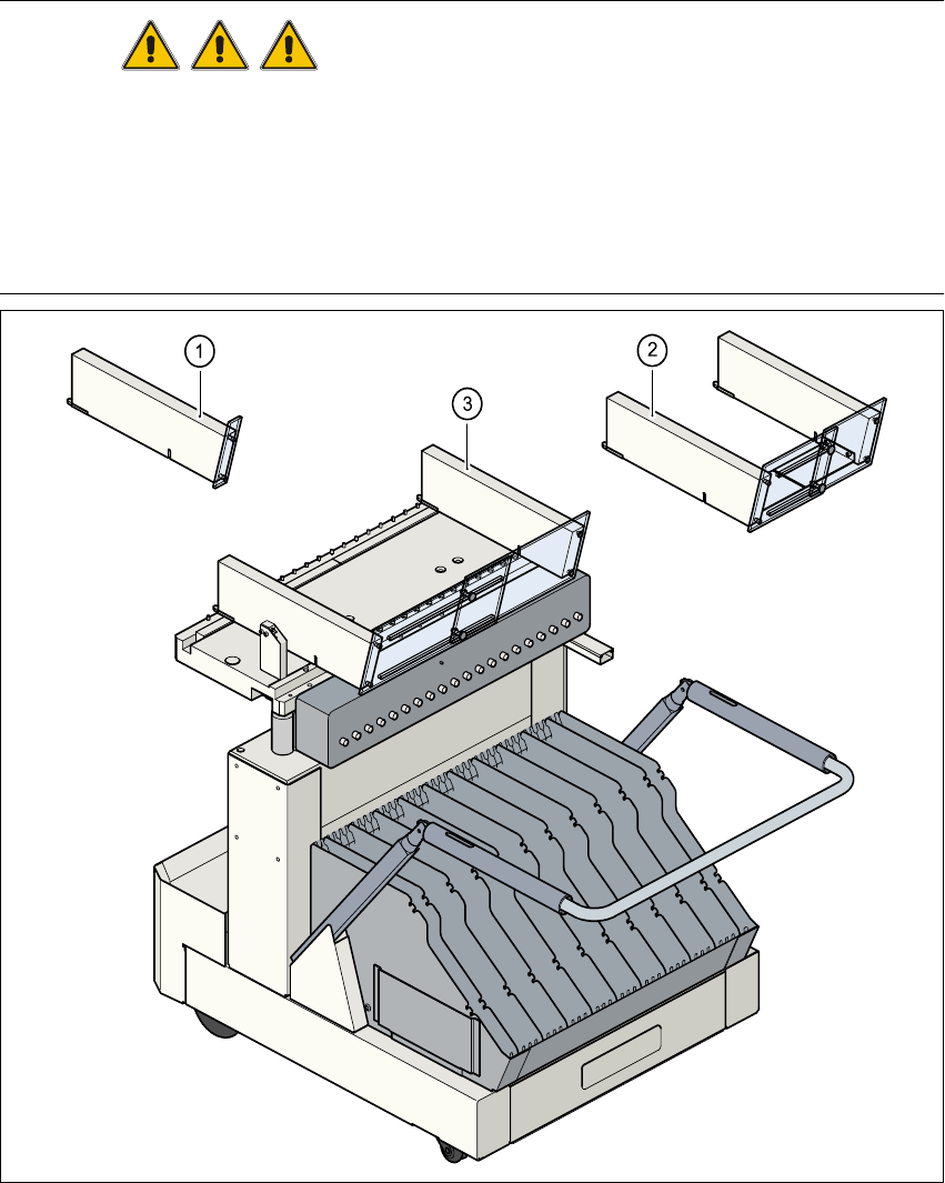
2.2.5 Guard on the component table locations
DANGER
All locations must be equipped with feeders in order to guarantee operational reliability. If there
are not enough feeders available, a guard ("feeder dummy") must be fitted in place of the feeder.
The following variants can be used:
Item no. 00116820-01 SIPLACE guard for 1 location
Item no. 00116821-01 SIPLACE guard for 6-10 locations
Item no. 00116822-01 SIPLACE guard for 11-20 locations 2
Fig. 2.2 - 6 Guard
(1) Guard for location 1 (2) Guard for 6 to 10 locations
(3) Guard for 11 to 20 locations 2
2 Operational Safety User Manual SIPLACE S-23 HM
2.3 Residual voltages in the servo unit and discharge times Software Version SR.406.xx 02/00 US Edition
84
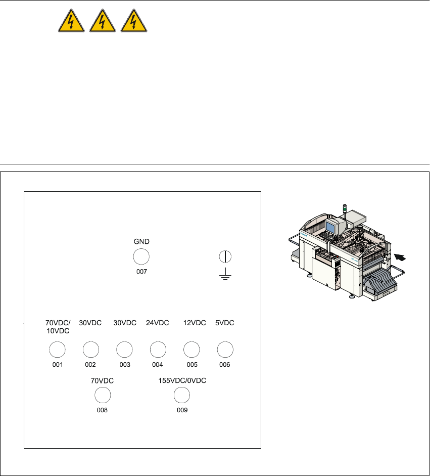
2.3 Residual voltages in the servo unit and discharge
times
When the emergency stop mushroom-head push-button is pressed or the placement system is
switched off, the electrolytic capacitors quickly discharge to safe residual voltage levels via
switched resistors on the discharge board (00308443-xx).
The voltages can be tapped off at test sockets 001 - 009 on the voltmeter unit in the servo unit.2
DANGER Automatic placement systems from the SIPLACE family are
powered with 3 x 400 VAC (3 x 208 VAC for the U.S.A. version) ± 5 %, 50/60 Hz main power volt-
age. This means that parts of the system carry potentially fatal voltages - even when switched off
at the main switch.
Death, serious injury or considerable damage may result if these placement systems are handled
incorrectly. Always follow the applicable accident prevention and DIN regulations (particularly
EN 60204, part 1).
The guard over the servo unit must ONLY be opened by appropriately qualified and trained per-
sonnel. 2
Fig. 2.3 - 1 Test sockets on the voltmeter unit in the servo unit
un-
switched
switched
Servo
unit

User Manual SIPLACE S-23 HM 2 Operational Safety
Software Version SR.406.xx 02/00 US Edition 2.3 Residual voltages in the servo unit and discharge times
85
2.3.1 Operating voltages, residual voltages and discharge times after pressing
the emergency stop mushroom-head push-button
2
2.3.2 Residual voltages and discharge times after switching off at the main switch
2
CAUTION To avoid losing data, evaluate the following criteria before switching off your
automatic placement system (apart from in emergencies):
– Has the placement system finished transmitting machine, set-up and working data?
– Has the placement system finished processing the PCB?
– Has the placement system completed the run-up phase?
– Has the Windows NT operating system been shut down correctly? 2
Test socket 00X
measured at 007
(GND)
Voltage
in normal mode
Residual voltage
after emerg. stop
Discharge times
of electrolytic
capacitors at 12 VDC
001 70 VDC 10 VDC < 2 sec
002 30 VDC 30 VDC –
003 30 VDC < 12 VDC < 2 sec
004 24 VDC 24 VDC –
005 12 VDC 12 VDC –
006 5 VDC 5 VDC –
008 70 VDC 10 VDC < 2 sec
009 155 VDC 10 VDC < 1 sec
Tab. 2.3 - 1 Operating voltages, residual voltages and discharge times after pressing the emergency stop
mushroom-head push-button
Test socket 00X
measured at 007 (GND)
Residual voltage
when main switch is off
Discharge times of electrolytic
capacitors at 12 VDC
001 < 12 VDC < 2 sec
002 < 12 VDC < 2 sec
003 < 12 VDC < 2 sec
004 0 VDC –
005 0 VDC –
006 0 VDC –
008 < 12 VDC < 2 sec
009 < 12 VDC < 1 sec
Tab. 2.3 - 2 Residual voltages and discharge times after switching off at the main switch