SIPLACE S-23 HM.pdf - 第87页
User Manual SIPLAC E S-23 HM 2 Operational Safety Software Version SR.406.xx 02/00 US Edition 2.5 Energy state of t he machine after switching off at the main switch 87 2.5 Energy st ate of the machine after switching of…
2 Operational Safety User Manual SIPLACE S-23 HM
2.4 Disabling the compr. air supply and discharging the pressure Software Version SR.406.xx 02/00 US Edition
86
2.4 Disabling the compr. air supply and discharging
the pressure
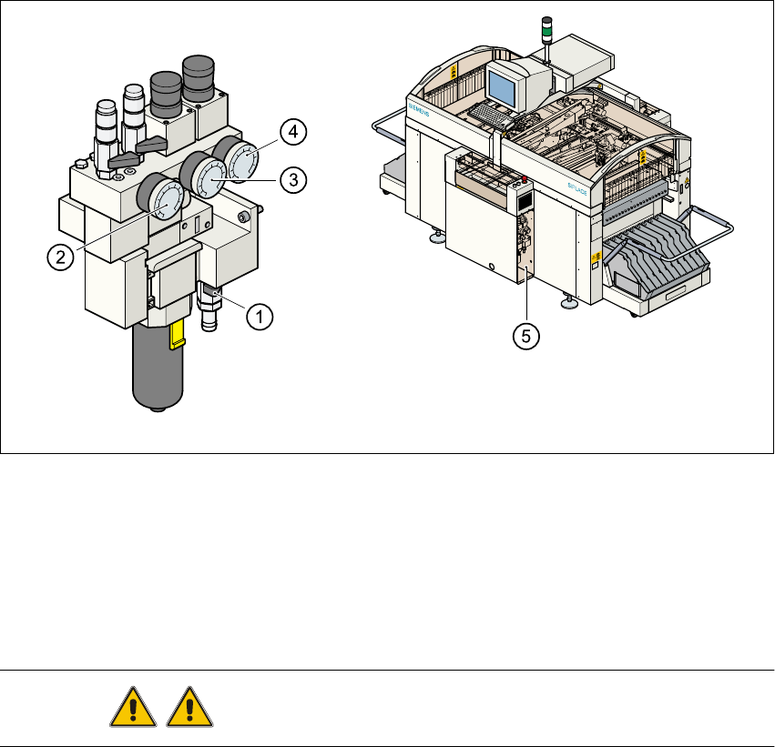
The compressed air working pressure is set to 5.1 bar, although it may fluctuate between 5.0 and
5.3 bar. The position of the compressed air unit is indicated by item 5 in Fig. 2.4 - 1. The com-
pressed air supply to the machine can be interrupted using the shut-off valve (item 1 in
Fig. 2.4 - 1). 2
– You must remove the cover plate to use the shut-off valve.
– Turn the lever on the shut-off valve (item 1 in Fig. 2.4 - 1) from the vertical to the horizontal
position.
– Watch the working pressure gauge (item 2 in Fig. 2.4 - 1) and the pressure gauges for the com-
pressed air supply to the component tables and tape cutters or to the stopper (item 3 or 4 in
Fig. 2.4 - 1). When the automatic placement system is switched on, the pressure discharges
to 0 bar within 1 minute.
2
Fig. 2.4 - 1 Compressed air unit on the automatic placement system
WARNING Never disconnect compressed air lines while they are pressurized.2
(1) Shut-off valve lever in the CLOSED position
(2) Working pressure gauge
(3) Pressure gauge for CO tables and tape cutters working pressure
(4) Pressure gauge for the PCB stopper working pressure
(5) Position of the compressed air unit
User Manual SIPLACE S-23 HM 2 Operational Safety
Software Version SR.406.xx 02/00 US Edition 2.5 Energy state of the machine after switching off at the main switch
87
2.5 Energy state of the machine after switching off at
the main switch
DANGER
Automatic placement systems from the SIPLACE family are powered with 3 x 400 V or 3 x
208 VAC (U.S.A. version) ± 5 %, 50/60 Hz mains voltage. This means that parts of the system
carry potentially fatal voltages - even when switched off at the main switch. Death, serious injury
or considerable damage may result if these placement systems are handled incorrectly.
Always follow the applicable accident prevention and DIN regulations (particularly EN 60204,
part 1). The guards over the control and servo units must ONLY be opened by appropriately qual-
ified and trained personnel. 2
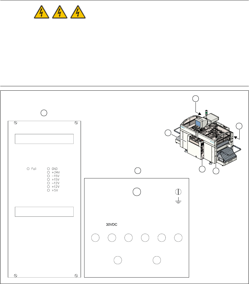
Fig. 2.5 - 1 Position of the control unit, servo unit, main switch, service socket and compr. air unit
1 Main switch Q1 2 Compressed air unit
3 Service socket 4 Servo unit
5 Control unit 6 S23 HM power supply for control unit
7 Measuring unit, servo unit
GND
007
001 002 003 004 005
006
008
009
70VDC/
10VDC
30VDC 24VDC 12VDC 5VDC
70VDC
155VDC/0VDC
6
7
5
4
3
2
1
un-
switched
switched
2 Operational Safety User Manual SIPLACE S-23 HM
2.5 Energy state of the machine after switching off at the main switch Software Version SR.406.xx 02/00 US Edition
88
2.5.1 Placement system switched off at the main switch, but still connected ...
The following table specifies the voltages of assemblies when the automatic placement system is
switched off at the main switch, but still connected to the mains supply. 2
2.5.2 Placement system switched off at the main switch and disconnected ...
The automatic placement system is unpowered, apart from slight residual voltages in the servo
unit. 2
2.5.3 Compressed air conditions in the machine after switching off at the main
switch
When the system is switched off at the main switch (item 1 in Fig. 2.5 - 1) or if the power supply
fails, the electrically-controlled main valve Y1 of the compressed air unit closes (Fig. 2.4 - 1,
page 86 ). The pressure will drop to 0 bar within 5 seconds. 2
Assembly Voltage
Main power filter Z1
Terminals L1, L2, L3
3 x 400 VAC (3 x 208 VAC)
Service socket
230 VAC(115 VAC)
Main switch Q1
Terminals 1, 3, 5
Terminals 2, 4, 6
3 x 400 VAC (3 x 208 VAC)
0 VAC
Servo unit (Item 7 in Fig. 2.5 - 1)
Test socket 001
Test socket 002
Test socket 003
Test socket 004
Test socket 005
Test socket 006
Test socket 008
Test socket 009
GND 007
< 12 VDC
< 12 VDC
< 12 VDC
0 VDC
0 VDC
0 VDC
< 12 VDC
< 12 VDC
Control unit (Item 6 in Fig. 2.5 - 1)
Test socket 5 V
Test socket + 12 V
Test socket – 12 V
Test socket + 15 V
Test socket – 15 V
Test socket + 24 V
GND
0 VDC
0 VDC
0 VDC
0 VDC
0 VDC
0 VDC
Tab. 2.5 - 1 Voltages of assemblies when the automatic placement system is switched off at the main switch,
but still connected to the main power