D3操作手册.pdf - 第28页
28 Comp onent Fee ding Waffle-Pack Tray Holder Description The w af fle- pack tra y ho ld er is a device for holding JEDEC trays used to supply compo- nents. The holder is placed on the component table like a feeder mo d…
27
Component Feeding
Dummy Feeder Modules
Danger
To ensure that your SIPLACE
placement machine runs
safely, a feeder must be
assigned to every location on
the component changeover
table. If you do not have
enough feeder modules,
then you should use dummy
feeder modules as space
holders.
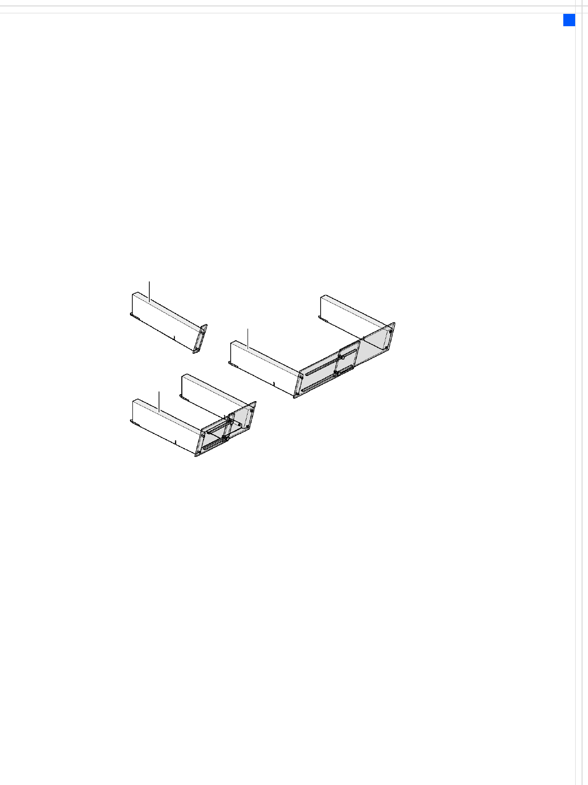
The following dummy feeder module variants are available for
component changeover tables:
SIPLACE dummy feeder module for 1 location
SIPLACE dummy feeder module for 6 to 10 locations
SIPLACE dummy feeder module for 11 to 20 locations
Dummy feeder module for 1 location
Dummy feeder module for
6 - 10 locations
Dummy feeder module for
11 - 20 locations
28
Component Feeding
Waffle-Pack Tray Holder
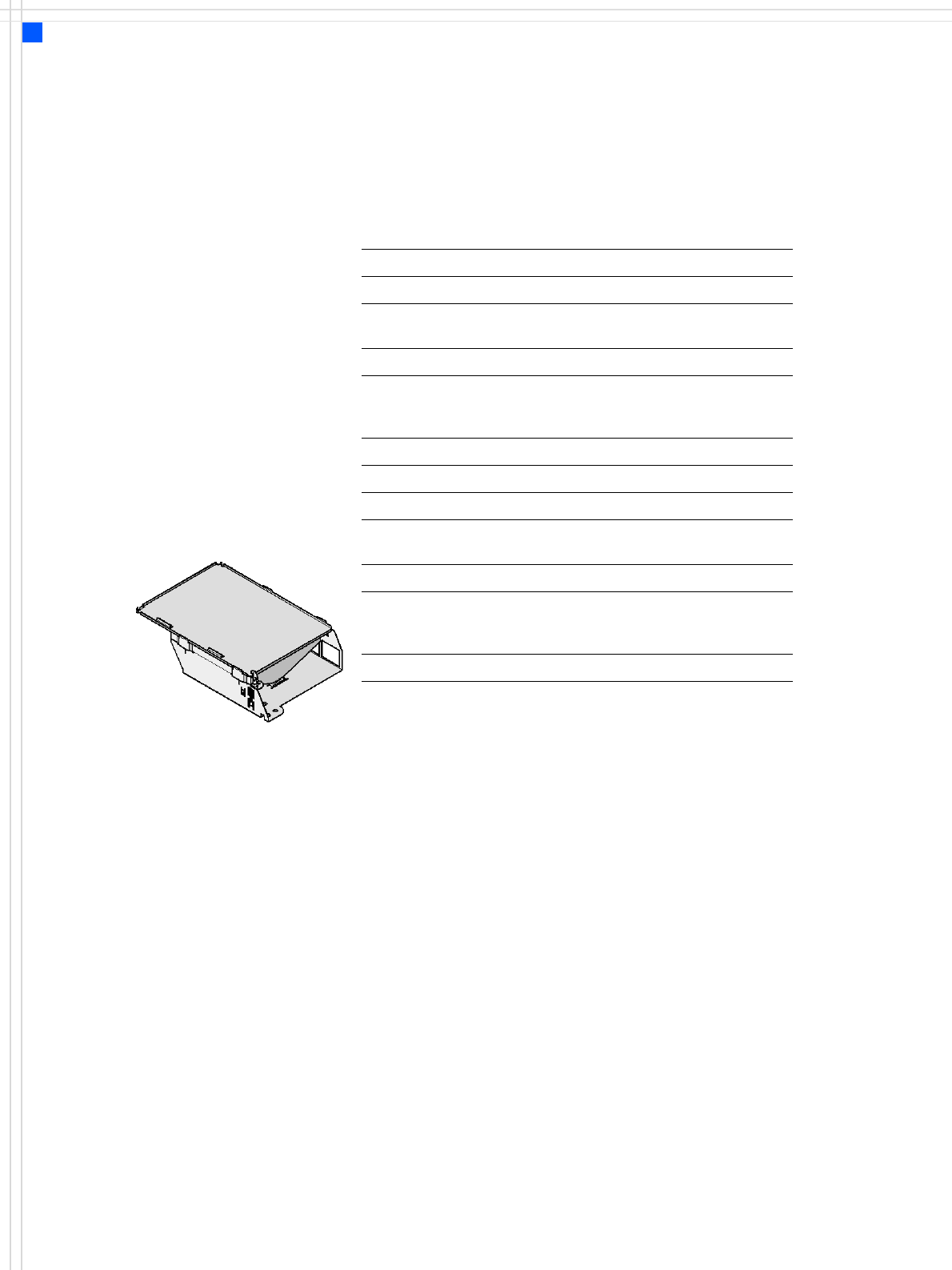
Description
The waffle-pack tray holder is
a device for holding JEDEC
trays used to supply compo-
nents. The holder is placed
on the component table like
a feeder module and the
waffle-pack trays are
changed manually.
The tray holder set-up is rec-
ommended if there are just a
few component types to be
placed from a waffle-pack
tray.
Technical data
Waffle-pack tray holder for large waffle-pack trays
Dimensions (LxWxH) 425 x 264 x 113 mm³
Locations filled on the
component table
9
Possible positions Locations 2 and 4
Software
Station software
Programming system
SR.602.xx or later
SIPLACE Pro 3.0 or later
Range of placement heads TwinHead, C&P6, C&P12
Waffle-pack tray holder for small waffle-pack trays
Dimensions (LxWxH) 425 x 140 x 113 mm³
Locations filled on the component
table
5
Possible positions Locations 2 and 4
Software
Station software
Programming system
SR.602.xx or later
SIPLACE Pro 3.0 or later
Range of placement heads TwinHead, C&P6, C&P12
Waffle-pack tray holder
29
Component Feeding
Matrix Tray Changer
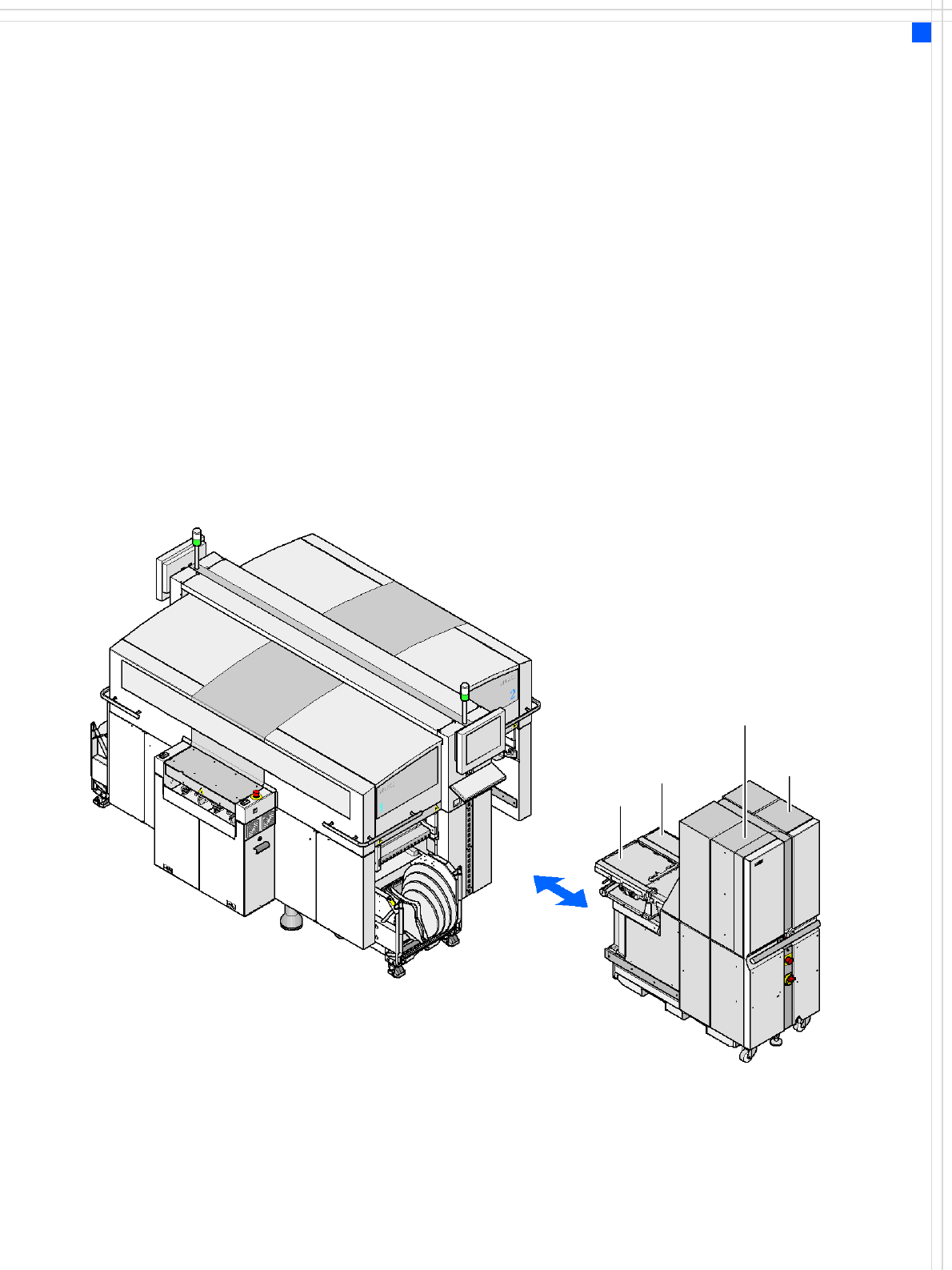
Description
For numerous tray fed com-
ponents we recommend an
automatic tray change using
a matrix tray changer (MTC).
The MTC set-up is precisely
matched to the placement
sequence in order to opti-
mize the timings and dis-
tances traveled.
Two bins with component
trays move independently of
one another in the vertical
direction until the desired
magazine is within the range
of the feed axis. The horizon-
tal feed axis transports the
tray from the tray supply to
within the range of the place-
ment head. The first maga-
zine is made available as
soon as a PCB moves onto the
PCB conveyor, and valid
panel and set-up data is avail-
able. All other magazine
changes are carried out time-
neutrally during the place-
ment process. The maga-
zines can be refilled without
stopping the machine.
Defective components are re-
turned to the original tray.
Tray supply 2
Tray supply 1
Feed axis 1
Feed axis 2