D3操作手册.pdf - 第6页
6 Placement principle Collect & Plac e Machine Description Extensions Extensions The options availa ble to ex- tend the f unctionality of the placement m achine includ e the following: • Additional component changeov…
5
Machine Description
Overview
Description
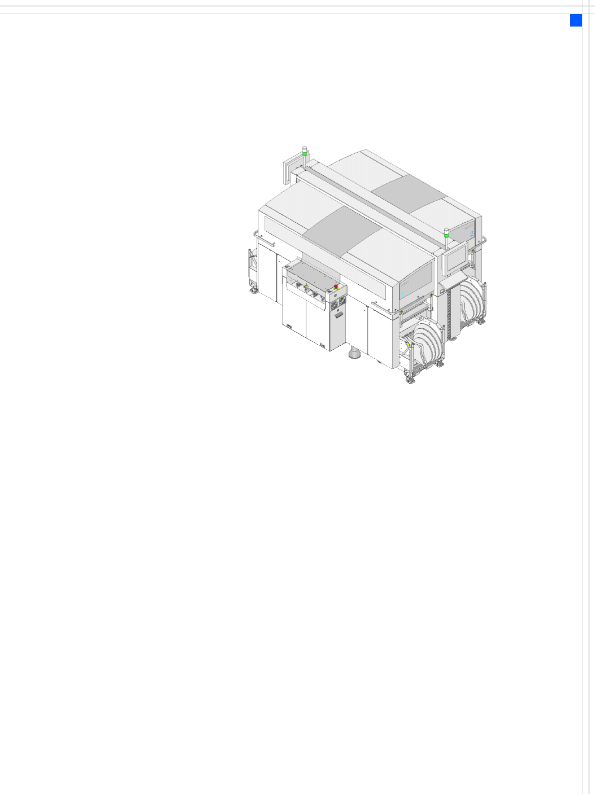
The SIPLACE D3 placement
system is particularly suit-
able for applications that
demand a high level of flexi-
bility, utmost precision, and
a high placement rate. Two
placement methods are
used:
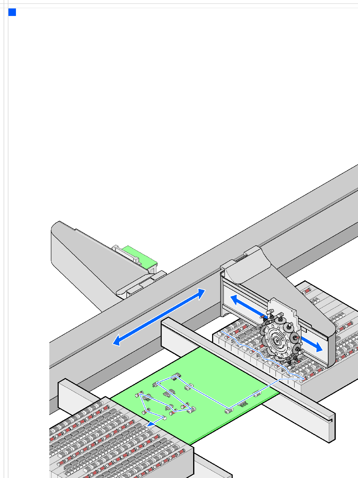
•the Collect&Place
method for high-speed
placement of standard
components (see diagram
on page 6)
•the Pick&Place method
for fast placement of spe-
cial fine-pitch and super-
fine pitch components
The D3 placement system
has three gantries driven by
linear motors. The gantries
can be quickly and accurately
positioned in the X and Y
directions. There is a place-
ment head on each gantry.
The following placement
head configurations are pos-
sible:
Placement area 1
• two 12-nozzle Collect &
Place heads or
• two 6-nozzle Collect &
Place heads or
• one 6-nozzle and one 12-
nozzle Collect&Place head
Placement area 2
•TwinHead
The head modularity prin-
ciple allows the placement
heads to be reconfigured to
suit changing requirements.
The table "Technical Data" on
page 7 contains a list of the
possible placement head
configurations and the
resulting placement rate.
The moving head picks up
the components from their
stationary feeder, and places
them on the PCB, which is
also stationary. This proven
SIPLACE principle has many
advantages:
• Short down times for refill-
ing or splicing
• Even the smallest compo-
nents are picked up reli-
ably
• The components cannot
slip on the PCB
• Minimal traversing paths
High flexibility, cost-effec-
tiveness and set-up reliability
guarantee that the SIPLACE
D3 placement system will be
highly productive. The mini-
mal down times increase
utilization, thus further in-
creasing productivity.
6
Placement principle
Collect & Place
Machine Description
Extensions
Extensions
The options available to ex-
tend the functionality of the
placement machine include
the following:
• Additional component
changeover tables in-
crease machine utilization
since set-up times can be
reduced by carrying out
preliminary set-up off the
machine.
• Large and sensitive fine-
pitch components can be
supplied in trays by a
matrix tray changer.
• The dual conveyor also in-
creases machine utiliza-
tion by eliminating non-
productive PCB transport
times.
• Automatic nozzle chang-
ers speed up and optimize
the nozzle configuration
process.
• PCB barcode scanners
allow the production set-
up to be changed over
when triggered by a new
product.
• Component barcode scan-
ners optimize the set-up
and refill checks.
• The productivity lift imple-
ments the concept of par-
allel placement, and thus
improves the ratio be-
tween productive and
non-productive times.

7
Machine Description
Technical Data
Types of placement head 12-nozzle Collect & Place head (C&P12)
6-nozzle Collect & Place head (C&P6)
SIPLACE TwinHead (TH)
Number of gantries 3 (see Fig. page 9)
Placement head configu-
ration and placement
rate
a
(Benchmark test)
a) According to the Definition in the SIPLACE Scope of Service and Delivery
Placement area 1 Placement area 2 Placement rate
C&P12 / C&P12 TH 30,100 comp./h
C&P12 / C&P6 TH 24,000 comp./h
C&P6 / C&P12 TH 24,000 comp./h
C&P6 / C&P6 TH 22,000 comp./h
Placement positions 6.000 / gantry for the Collect & Place head
Range of components 0.4 x 0.2 mm² (01005)
b
, 0.6 x 0.3 mm² (0201)
c
to 85 x 85 mm² / 125 x 10 mm²
max. 200 x 125 mm² (with restrictions)
b) 01005 optional, from April 2007
c) with 0201 package
Component height C&P12: 6 mm (larger heights on request)
C&P6: 8.5 mm (larger heights on request)
TH: 25 mm
Placement accuracy /
angular accuracy
C&P12: ± 45 μm, ± 0.5° / (3σ), ± 60 μm, ± 0.7° / (4σ)
(standard camera)
C&P12: ± 41 μm, ± 0.5° / (3σ), ± 55 μm, ± 0.7° / (4σ)
(high-resolution camera)
C&P6: ± 45 μm, ± 0.2° / (3σ), ± 60 μm, ± 0.3° / (4σ)
TH: ± 26 μm, ± 0.05° / (3σ), ± 35 μm, ± 0.07° / (4σ)
(Fine-Pitch Camera)
± 22 μm, ± 0.05° / (3σ), ± 30 μm, ± 0.07° / (4σ)
(Flip-Chip Camera)
Component Feeding 4 component changeover tables with tape roll holders and
integral waste containers
15 slots, 30 mm wide per changeover table or matrix tray
changer, rather than a component changeover table
(location 2)
Feeder module types Tapes, bulk cases, stick magazines, application-specific OEM
feeder modules, surftape feeder modules (8, 12, 16 mm),
waffle-pack trays
Feeding capacity 60 tape feeder modules 3 x 8 mm S (180 tracks)
60 tape feeder modules 2 x 8 mm S (120 tracks)
60 tape feeder modules 12/16 mm S (60 tracks)
40 tape feeder modules 24/32 mm S (40 tracks)
28 tape feeder modules 44 mm S (28 tracks)
24 tape feeder modules 56 mm S (24 tracks)
20 tape feeder modules 72 mm S (20 tracks)
16 tape feeder modules 88 mm S (16 tracks)