D3操作手册.pdf - 第8页
8 Machine Description Technical Data PCB format (LxW) PLEASE NOTE: With PCB widths > 450 mm make sure that t he peripheral modules are also able to pr ocess these widths. Single con veyor 50 x 50 mm² t o 450 x 460 mm²…

7
Machine Description
Technical Data
Types of placement head 12-nozzle Collect & Place head (C&P12)
6-nozzle Collect & Place head (C&P6)
SIPLACE TwinHead (TH)
Number of gantries 3 (see Fig. page 9)
Placement head configu-
ration and placement
rate
a
(Benchmark test)
a) According to the Definition in the SIPLACE Scope of Service and Delivery
Placement area 1 Placement area 2 Placement rate
C&P12 / C&P12 TH 30,100 comp./h
C&P12 / C&P6 TH 24,000 comp./h
C&P6 / C&P12 TH 24,000 comp./h
C&P6 / C&P6 TH 22,000 comp./h
Placement positions 6.000 / gantry for the Collect & Place head
Range of components 0.4 x 0.2 mm² (01005)
b
, 0.6 x 0.3 mm² (0201)
c
to 85 x 85 mm² / 125 x 10 mm²
max. 200 x 125 mm² (with restrictions)
b) 01005 optional, from April 2007
c) with 0201 package
Component height C&P12: 6 mm (larger heights on request)
C&P6: 8.5 mm (larger heights on request)
TH: 25 mm
Placement accuracy /
angular accuracy
C&P12: ± 45 μm, ± 0.5° / (3σ), ± 60 μm, ± 0.7° / (4σ)
(standard camera)
C&P12: ± 41 μm, ± 0.5° / (3σ), ± 55 μm, ± 0.7° / (4σ)
(high-resolution camera)
C&P6: ± 45 μm, ± 0.2° / (3σ), ± 60 μm, ± 0.3° / (4σ)
TH: ± 26 μm, ± 0.05° / (3σ), ± 35 μm, ± 0.07° / (4σ)
(Fine-Pitch Camera)
± 22 μm, ± 0.05° / (3σ), ± 30 μm, ± 0.07° / (4σ)
(Flip-Chip Camera)
Component Feeding 4 component changeover tables with tape roll holders and
integral waste containers
15 slots, 30 mm wide per changeover table or matrix tray
changer, rather than a component changeover table
(location 2)
Feeder module types Tapes, bulk cases, stick magazines, application-specific OEM
feeder modules, surftape feeder modules (8, 12, 16 mm),
waffle-pack trays
Feeding capacity 60 tape feeder modules 3 x 8 mm S (180 tracks)
60 tape feeder modules 2 x 8 mm S (120 tracks)
60 tape feeder modules 12/16 mm S (60 tracks)
40 tape feeder modules 24/32 mm S (40 tracks)
28 tape feeder modules 44 mm S (28 tracks)
24 tape feeder modules 56 mm S (24 tracks)
20 tape feeder modules 72 mm S (20 tracks)
16 tape feeder modules 88 mm S (16 tracks)

8
Machine Description
Technical Data
PCB format
(LxW)
PLEASE NOTE:
With PCB widths > 450 mm make
sure that the peripheral modules
are also able to process these
widths.
Single conveyor
50 x 50 mm² to 450 x 460 mm²
50 x 80 mm² to 610 x 460 mm² (Long board option)
(Width up to 508 mm available on request)
Flexible dual Conveyor
50 x 50 mm² to 450 x 216 mm²
50 x 80 mm² to 610 x 216 mm² (Long board option)
(Width up to 250 mm available on request)
Flexible dual conveyor in Single conveyor mode
50 x 50 mm² to 450 x 380 mm²
50 x 80 mm² to 610 x 380 mm² (Long board option)
(Width up to 450 mm available on request)
PCB thickness 0.3 - 4.5 mm (thicker PCBs on request)
Electrical ratings and
compressed air supply
see page 40
Dimensions of the placement
systems
see figure page 43
9
Placement area 2
Placement area 1
C&P6
C&P12
C&P6
C&P12
TH
Gantry 3
Gantry 1
Gantry 4
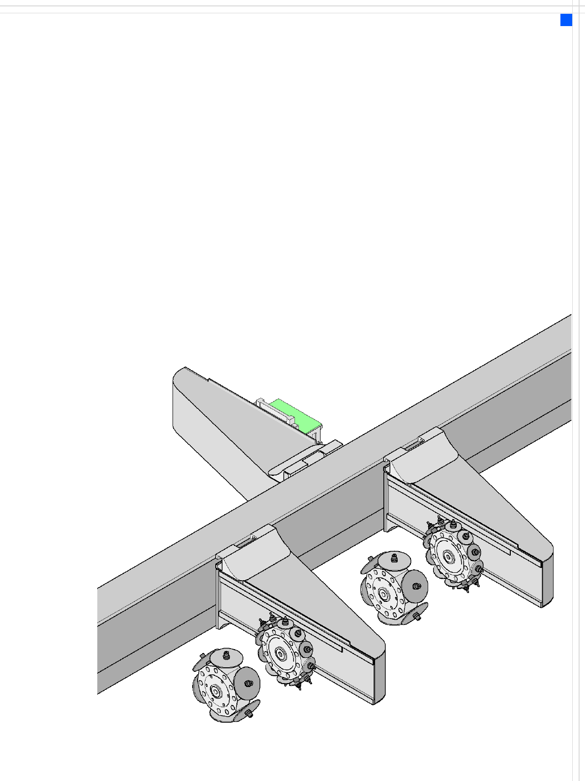
Placement Heads
Head Modularity
Description
One key advantage of the
SIPLACE machines is its head
modularity. The placement
heads on the D3 machines
are configurable:
Placement area 1
• two 12-nozzle Collect &
Place heads or
• two 6-nozzle Collect &
Place heads or
• one 6-nozzle and one 12-
nozzle Collect&Place head
Placement area 2
•TwinHead
When you order a SIPLACE D3
placement system, you can
select the ideal head configu-
ration for your needs. The
placement system will then
be configured and supplied
as per your order.
There is also a reconfigura-
tion kit if you wish to change
the placement head locally.
This package contains assem-
bly parts, cables, etc, in addi-
tion to the placement head.
Head modularity provides an
easy way to match the place-
ment system to your produc-
tion needs without having
to invest in additional ma-
chines.