00197089-02_AI_EA-Verl_X-Serie_S_de_en.pdf - 第60页
Installation Overview of Conversion (Before/A fter) 3.2.1 Input Conveyor – Con veyor Side A 60 Extension Input/Output Conveyor and Hand Guard Ein-/ 3.2 3 . 2 O v e r v ie w o f C o n v e r s io n ( B e f o r e / A f t e …
Installation
Overview of Conveyor Sides
Extension Input/Output Conveyor and Hand Guard Ein-/Ausgabebandverlängerung und Eingreifschutz 59
3
3 Installation
Installation
3.1
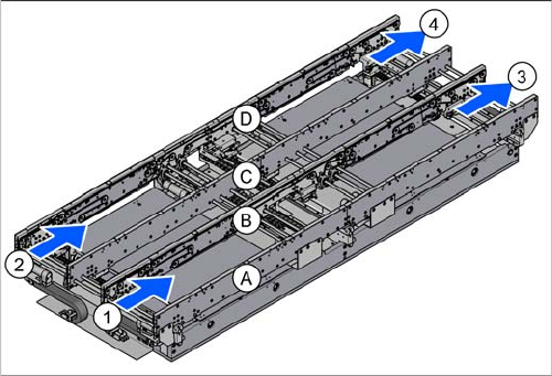
3.1 Overview of Conveyor Sides
Overview of Conveyor Sides
1. Input side, conveyor lane 1
2. Input side, conveyor lane 2
3. Output side, conveyor lane 1
4. Output side, conveyor lane 2
(A) to (D) = conveyor side A to D
Installation
Overview of Conversion (Before/After) 3.2.1 Input Conveyor – Conveyor Side A
60 Extension Input/Output Conveyor and Hand Guard Ein-/
3.2
3.2 Overview of Conversion (Before/After)
Overview of Conversion (Before/After)
The following diagrams give an overview of all required conversion steps for the conveyor side.
3.2.1
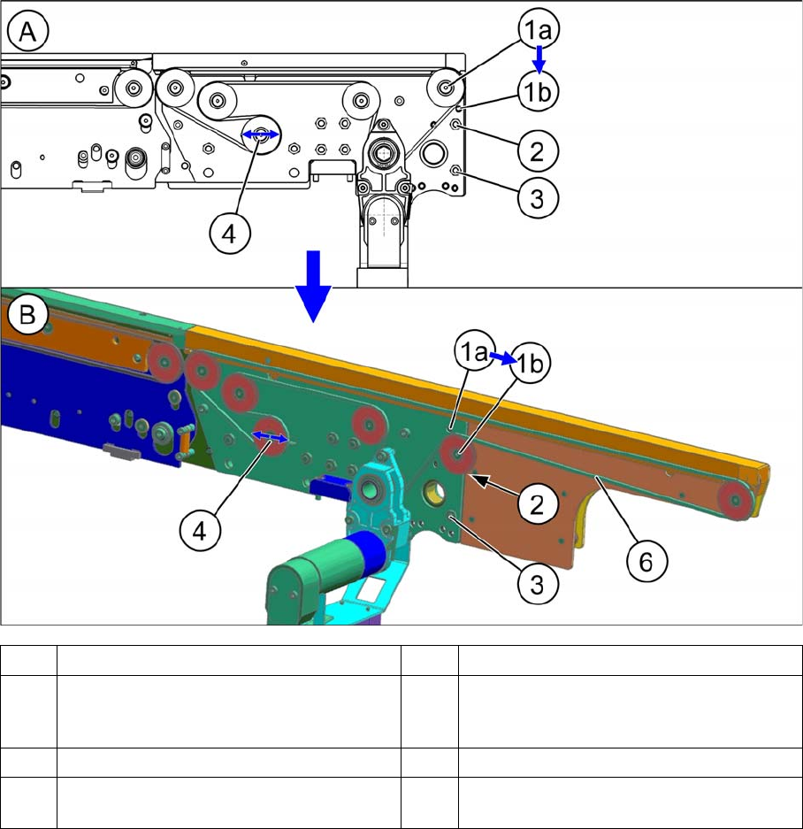
3.2.1 Input Conveyor – Conveyor Side A
Input Conveyor – Conveyor Side A
A Conveyor side without extension B Conveyor side with extension
1 The idler pulley is converted from (1a) to
(1b).
2 The screw M5x16 (TX25) with nut is re-
placed with a shorter screw M5x14.7 with-
out nut.
3 The screw M5x16 (TX25) with nut remains. 4 Idler (loosen only)
6 Measurement point for belt tension: 85+-
9Hz
Installation
3.2.2 Input Conveyor – Conveyor Side B Overview of Conversion (Before/After)
Extension Input/Output Conveyor and Hand Guard Ein-/Ausgabebandverlängerung und Eingreifschutz 61
3.2.2
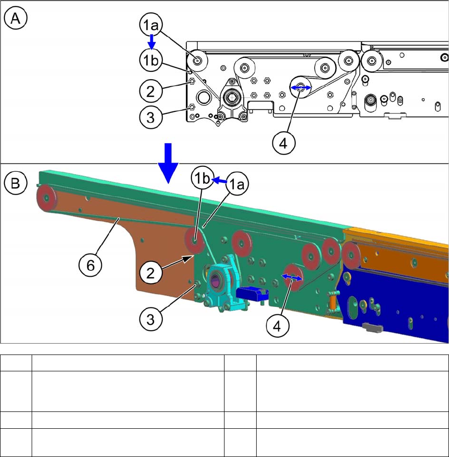
3.2.2 Input Conveyor – Conveyor Side B
Input Conveyor – Conveyor Side B
A Conveyor side without extension B Conveyor side with extension
1 The idler pulley is converted from (1a) to
(1b).
2 The screw M5x16 (TX25) with nut is re-
placed with a shorter screw M5x14.7 with-
out nut.
3 The screw M5x16 (TX25) with nut remains. 4 Idler (loosen only)
6 Measurement point for belt tension: 85+-
9Hz