00197089-02_AI_EA-Verl_X-Serie_S_de_en.pdf - 第73页
Installation 3.2.8 Output Conveyor – Conveyor Side D Fitting the Hand Guard Extension Input/Output Conveyor and Hand Guard Ein-/Ausga beband verlängerung und Eingreifschutz 73 3.5 3 . 5 F it t in g t h e H a n d G u a r …

Installation
Assembly of Input/Output Conveyor Extension 3.2.8 Output Conveyor – Conveyor Side D
72 Extension Input/Output Conveyor and Hand Guard Ein-/
► Thread the conveyor belt into the deflection pulleys and fix into place with the idler. For details of the
exact routing of the belt, refer to the diagrams in section "3.2 Overview of Conversion (Before/After)"
[➙60].
► Repeat these steps for all conveyor sides.
► Push the hexagonal shaft back to its original position and fix the hexagonal shaft bracket into place
with the plastic bearings. Retighten the fastening screws manually (hand-tight).
► Set the belt tensions at all new and loosened belts. For details of the correct values, refer to the rel-
evant diagrams in section "3.2 Overview of Conversion (Before/After)" [ ➙ 60].
Also observe section "4.1 Calculating the Belt Tension" [ ➙ 77].
CAUTION
Output conveyor (all sides)
Make sure that the old and new idlers do not touch one another.
► If the two idlers do touch after the belt tension has been set, check the position of the motor/
drive. This should be pressed slightly upwards during assembly. This allows the conveyor
belt enough play.
Installation
3.2.8 Output Conveyor – Conveyor Side D Fitting the Hand Guard
Extension Input/Output Conveyor and Hand Guard Ein-/Ausgabebandverlängerung und Eingreifschutz 73
3.5
3.5 Fitting the Hand Guard
Fitting the Hand Guard
NOTICE
Second person
► You may need to enlist the help of a second person for this job.
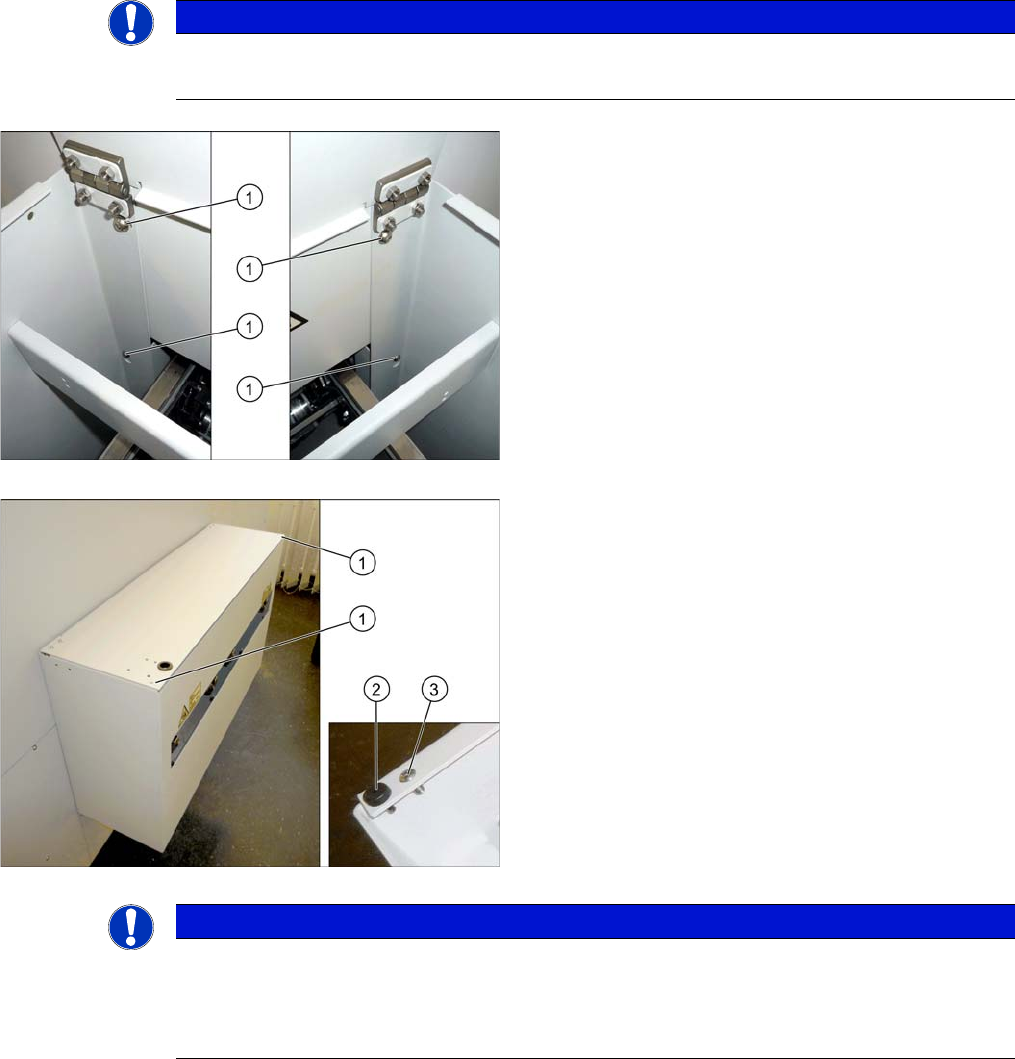
► Fix the hand guard into place on the machine, using
the 4 fastening screws (1). (washer M6, screw
[03042571-xx] M6x10)
Without PCB barcode:
If no PCB barcode has been fitted, this flap must be
screwed into place. Proceed as follows:
► Make sure that the two buffers (2) are fitted.
► Fix the flap to the two corners (1) using the screws
provided (3).
The installation of the hand guard is completed.
NOTICE
With PCB barcode:
If a PCB barcode is fitted into the hand guard, make sure you secure the flap with a Schmersal
switch.
► Read the "PCB Barcode" assembly instructions.
Installation
Final Work: 3.6.1 Teaching the PCB Sensors (SW70x)
74 Extension Input/Output Conveyor and Hand Guard Ein-/
3.6
3.6 Final Work:
Final Work:
► If you have dismantled the nozzle reject station, fix it back into place.
► If you have loosened the clamp, restore the clamping function.
► If you have loosened the fixed side, fix it back into place.
► Check the PCB sensors and calibrate these if needed (see section "3.6.1 Teaching the PCB Sensors
(SW70x)" [ ➙ 74]).
► Configure the installation (or removal) of the extension in the Sirio software.
3.6.1
3.6.1 Teaching the PCB Sensors (SW70x)
Teaching the PCB Sensors (SW70x)
Whenever you manually loosen the conveyor sides, you also need to reteach the light barrier sensors.
This is required because the light intensity depends on the conveyor width. Without teaching, the con-
veyor will show boards which are not present, preventing the conveyor from being referenced.
Teaching is performed automatically during operation.
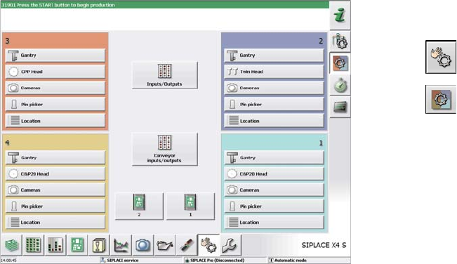
Procedure
► Switch over to the activity level "Service (customer)"
(or better still).
► Select .
► Select .
► Select Conveyor inputs/outputs.