00197089-02_AI_EA-Verl_X-Serie_S_de_en.pdf - 第76页
Installation Final Wo rk: 3.6.1 Teaching the PCB Sensors (SW70x) 76 Extension Input/Output Conveyor and Hand Guard Ein-/
Installation
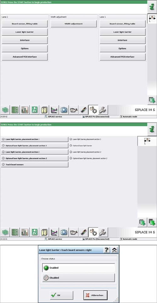
3.6.1 Teaching the PCB Sensors (SW70x) Final Work:
Extension Input/Output Conveyor and Hand Guard Ein-/Ausgabebandverlängerung und Eingreifschutz 75
► Select Laser light barrier at conveyor lane 1, enable
Teach board sensors and press the Start button on
the machine.
Disable this function again afterwards.
► For DC: select Laser light barrier at conveyor lane 2,
enable Teach board sensors and press the Start but-
ton on the machine.
Disable this function again.
Installation
Final Work: 3.6.1 Teaching the PCB Sensors (SW70x)
76 Extension Input/Output Conveyor and Hand Guard Ein-/
Appendix
Calculating the Belt Tension
Extension Input/Output Conveyor and Hand Guard Ein-/Ausgabebandverlängerung und Eingreifschutz 77
4
4 Appendix
Appendix
4.1
4.1 Calculating the Belt Tension
Calculating the Belt Tension
Example
Distance between the rollers: 235 mm
Calculation:
20000/235 = 85 (exactly 85.106…)
10 % of 85.106… = 8.5106…
Result:
Belt tension: 85 +/-9 Hz
NOTICE
For conveyor belt only
This calculation only applies to the conveyor belt.
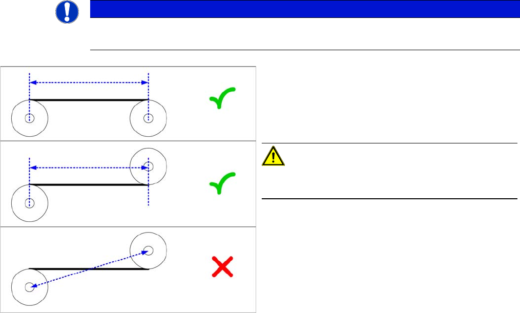
► Define the two deflection pulleys between which you
want to set the belt tension. If possible, avoid using
the idlers for this.
► Measure the distance between the two deflection pul-
leys parallel to the conveyor belt. (see diagram)
CAUTION!
Please note that it is not always possible to just measure
the deflection pulleys from center to center.
► Calculate the belt tension using the following formula:
20000 / Roller spacing [Hz]
The permissible tolerance is always 10 % of the calculat-
ed value.