00198481-01_Technical_Training_E_by_DEK_EN.pdf - 第38页
5 Gantry Systems 5.2 Camera System 38 Technical Training E by DEK 12/2017 5.2.2 Camera Functionality The function of the camera system is to supply a visual indication of screen to board alignment and board/screen inspec…
5 Gantry Systems
5.2 Camera System
Technical Training E by DEK 12/2017 37
5.2 Camera System
The camera system consists of the following sub-assemblies:
●
Digital Camera
●
PCI Interface card or Vision card(s) and
vision adaptor card
●
Camera "X" CAN servo motor assembly
(Node 8)
●
Camera "Y" CAN servo motor assembly
(Node 9)
●
X and Y drive belts
●
X and Y through beam opto home sensors
●
Board stop assembly
●
Board at stop reflective opto sensor
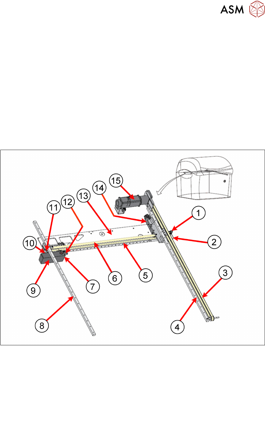
5.2.1 Main Overview
5.2.1.1 Camera Module (Rotary Drive)
Camera System Overview:
1. Camera Y Home Sensor 9. Camera
2. Camera Y Home flag 10. Camera X Home Flag
3. Camera Y Drive Belt 11. Camera X Home Sensor
4. Camera Y Linear Bearing 12. Board Stop extended Sensor
5. Camera X Linear Bearing 13. Camera axis beam
6. Camera X Drive Belt 14. Camera X Motor (Node 8)
7. Board at Stop Sensor 15. Camera Y Motor (Node 9)
8. Camera Y Linear Bearing

5 Gantry Systems
5.2 Camera System
38 Technical Training E by DEK 12/2017
5.2.2 Camera Functionality
The function of the camera system is to supply a visual indication of screen to board alignment and
board/screen inspection data to the machine PC enclosure.
The captured information supplied to the PC enclosure enables the processor to:
●
Align the screen to the product board.
●
Provide visual information for the user on the MMI monitor.
The camera assembly is driven by:
●
Rotary Servo Motors
The camera carriage is also used to transport the board stop and the underscreen cleaner.
The camera assembly travels in the X and Y axis to position the camera to carry out the following
functions:
●
Board Stop
●
Fiducial Capture - for screen to board alignment
●
Site Capture - Post Print Inspection
●
Moving the Underscreen Cleaner
The camera contains an optical unit for image focusing and a lighting unit for board and screen
illumination during fiducial and 2D camera capture operations.
The camera carriage also contains the following:
●
Camera Board Stop
●
Board at Stop sensor
●
Board Stop Extended Sensor
The camera board stop is a pneumatically driven unit which is lowered to stop the board in position
ready for clamping and vision alignment to take place.
When the board reaches the board stop, the opto sensor detects the board. This starts a timer
which stops the belts and clamps the board, when elapsed.
The board stop extended sensor is fitted to ensure that the board stop is raised before any camera
carriage movement is demanded.
The camera positions are referenced from the home position. Each camera axis only homes during
initialisation, which can be from power-up or exiting diagnostics.
The camera system also provides the drive mechanism for the under screen cleaner.
The camera system contains one of the following cameras:
●
Hawkeye 750
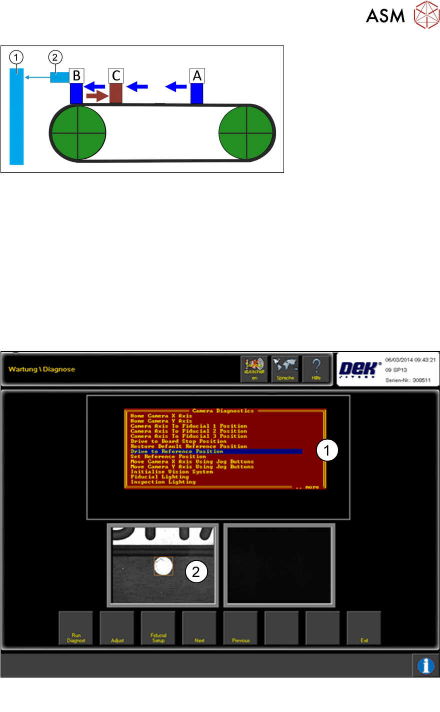
5.2.2.1 Zero Point (Homing Sequence)
The camera positions are all referenced from the Camera Reference Position (setting) which is
located on the front transport rail. This position is a set position measured from the Camera X and
Y home positions and allows for tolerances across machines. Each camera axis only homes during
initialisation, which can be from power-up or exiting diagnostics.
During the homing sequence the 2 vanes are driven slowly into the sensors.
Once the sensors are activated the motor changes direction and drives the vanes out of the
sensor. As soon as the sensors are de activated the home position is reached.
5 Gantry Systems
5.2 Camera System
Technical Training E by DEK 12/2017 39
1. Control (I/O Node or NM I/F card) 2. Sensor
A - Motor reverses towards sensor C - Motor drives forward until flag leaves sensor
B - Flag enters sensor D - Motor stops
The position of the sensors and vanes are fixed, therefore no adjustment is possible.
Camera Reference Position
The camera reference position is the orientation position for many of the machine processes and
functions, (PCB positioning, stencil alignment, cleaning, Hawkeye, stinger and so on).
The reference point can be set up in the Diagnostics Menu.
As of version 10 the reference point is set in the Calibrations Menu.
With the help of the jog function the camera can be driven to the required position and this can be
saved as the Camera Reference position.
1. Menu point drive to reference position
2. Reference point image