00198481-01_Technical_Training_E_by_DEK_EN.pdf - 第92页
10 Machine Modules 10.1 Stencil Mount 92 Technical Training E by DEK 12/2017 10.1.4 Screen Alignment The screen alignment consists of the following sub-assemblies: ● 3x screen actuators (Xf, Xr, Y) ● 2x chase clamps ● 4x…
10 Machine Modules
10.1 Stencil Mount
Technical Training E by DEK 12/2017 91
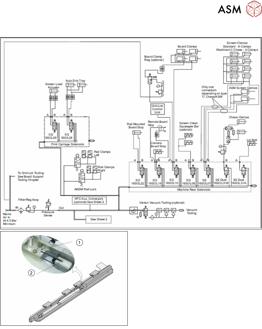
Adjustable Width Screen Mount Pneumatic
1. Cable Retainer Bracket
2. Pulley Retaining Pin
3. 2 way air driven pneumatic cylinder
4. With pressure reducer to protect string
10 Machine Modules
10.1 Stencil Mount
92 Technical Training E by DEK 12/2017
10.1.4 Screen Alignment
The screen alignment consists of the following sub-assemblies:
●
3x screen actuators (Xf, Xr, Y)
●
2x chase clamps
●
4x chase roller counter plates
●
Chase clamp air regulator
●
Dual stepper drive cards (X1 & X3)
Screen actuator
Replaced as complete assembly.
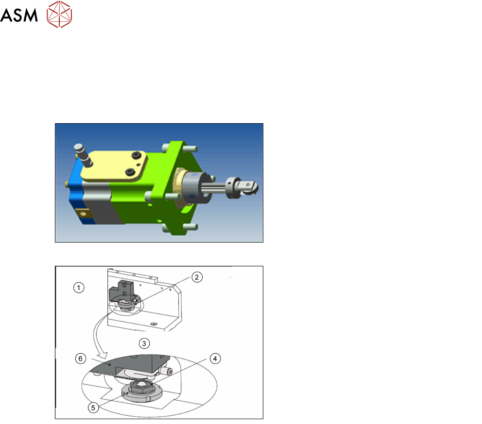
Chase Clamps
1. View on front Left or rear right printhead
2. Roller counter plate
3. View on roller bearing assembly
4. Roller bearing assembly
5. Locking nut
6. Chase clamp
The chase clamps consist of a pneumatic cylinder sitting on a plate with a rubber seal underneath.
●
Once the frame has been fixed in position the chase will clamp the screen in place.
●
There should be a force of 12kg.
●
There is a pneumatic regulator on the rear of the machine to adjust the force.
10 Machine Modules
10.1 Stencil Mount
Technical Training E by DEK 12/2017 93
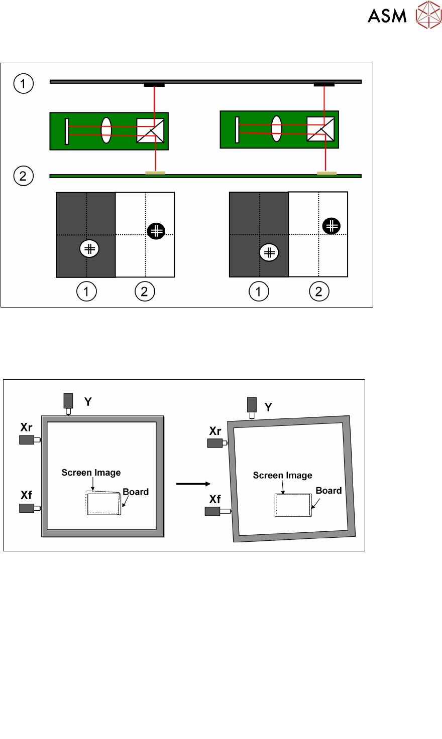
10.1.4.1 Screen Alignment Functionality
1.Stencil 2.Board
The camera captures each of the fiducials (screen and board) and sends the data to the processor.
The processor uses this data as well as the calibration data to calculate the amount of stencil
movement required to align the stencil to the board. The processor then tells the actuators to move
the print stencil in the X, Y and theta direction.
.
Limits of travel : Xf, Xr = ±9mm approx. Y = ±9mm approx.
Offsets : Y = ± 1mm X = ±1mm, theta ±1000aSec
The alignment system consists of three stepper motor driven linear actuators in contact with the
chase (adjustable stencil mount)
The actuators are configured in a three point contact arrangement and are controlled and driven
independently to give maximum flexibility in stencil movement.
The actual distance moved by the actuators will be determined by:
●
Distance between board and stencil
●
Camera scale and offset calibration factors
●
Applied offsets
●
Alignment weighting
●
Pitch of actuator lead screw
●
Step configuration of drive card
●
Smallest moveable distance
– 3.41 microns currently
– 0.4 microns with micro-step introduction